Brooks, Model 5850e – Brooks Instrument 5850E User Manual
Page 23
Brooks
®
Model 5850E
3-3
Section 3 Operation
Installation and Operation Manual
X-TMF-5850E-MFC-eng
Part Number: 541B102AHG
September, 2009
the control valve voltage during operation, also grounding this terminal will
cause the control valve to open independent of the command signal. Refer
to Section 2-11.
Remote Transducer Input
Accessed via terminal 5 on the Card Edge or Pin 15 on the D-Connector
version. This feature allows the use of the integral control electronics and
valve with the signal from an external 0-5 Vdc signal. The mass flow signal
from the Model 5850E is still available for process monitoring. Refer to
Section 2-9.
3-2 Operating Procedure
a. Apply power to the controller and allow approximately 45 minutes for
the instrument to warm-up and stabilize its temperature.
b. Turn on the gas supply.
c. Command 0% flow and observe the controllers output signal. If the
output is not 0 mVdc (±10 mVdc), check for leaks and if none are
found, refer to the re-zeroing procedure in Section 3-3.
d. Set the command for the desired flow rate to assume normal operation.
3-3 Zero Adjustment
Each Model 5850E is factory adjusted to provide a zero ±10 mVdc signal
at zero flow. The adjustment is made in our calibration laboratory which is
temperature controlled to 21.1°C (70°F ±2°F). After initial installation and
warm-up in the gas system, the zero flow indication may be other than the
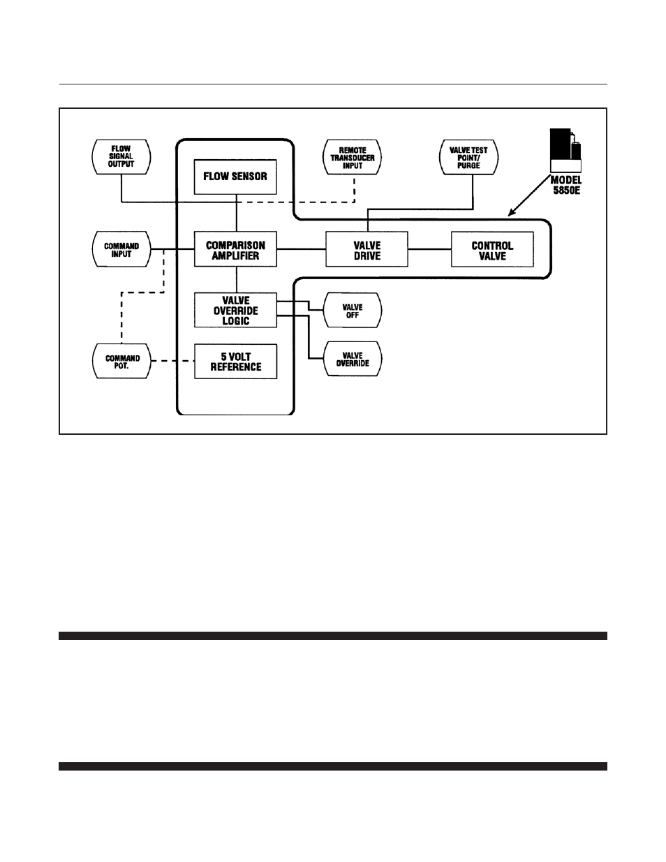
Figure 3-2 Flow Control System Block Diagram