Atec Rohde-Schwarz-SMU200A User Manual
Page 28
Version 08.00, January 2012
28
Rohde & Schwarz
R&S
®
SMU200A Vector Signal Generator
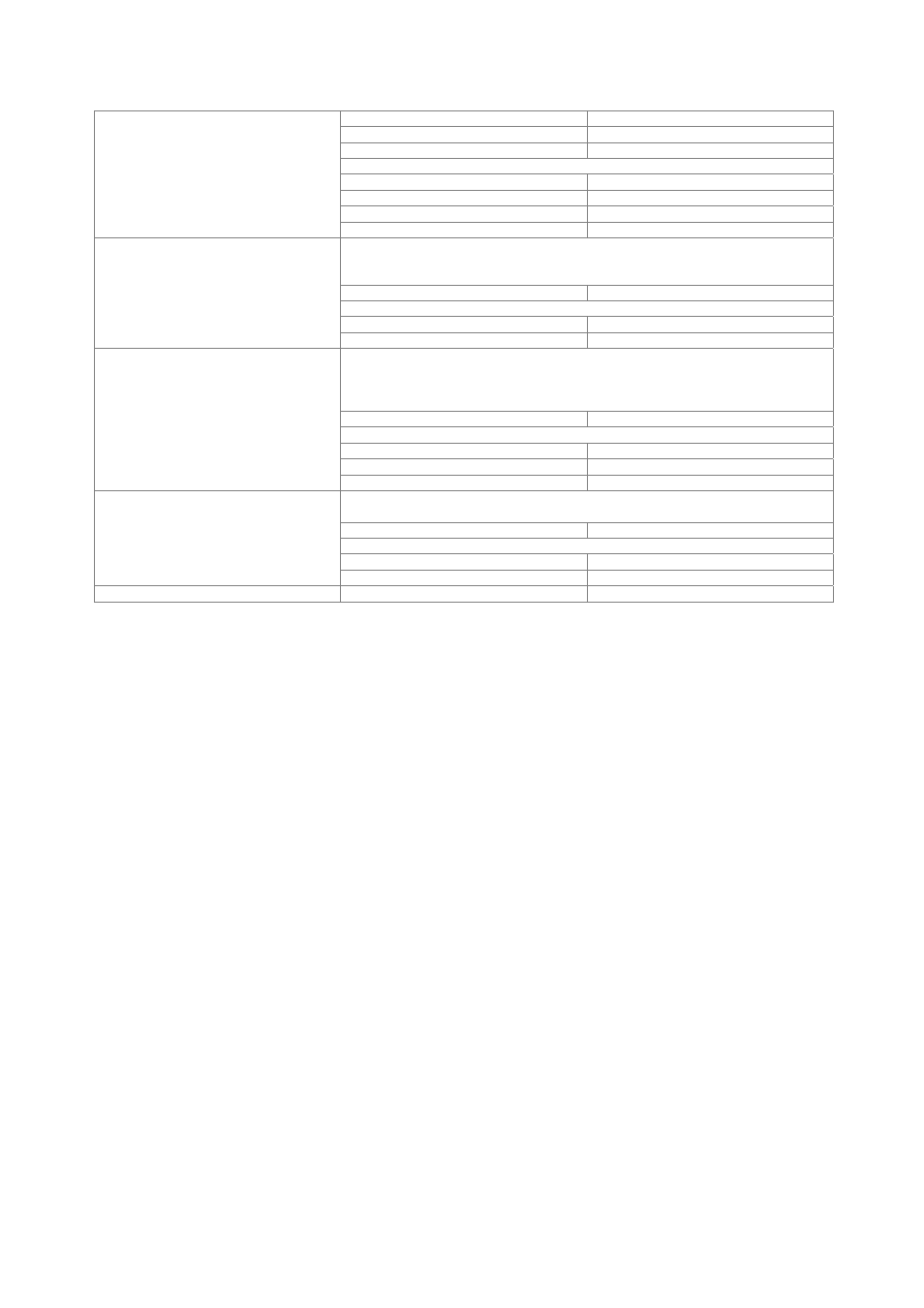
number 4
level LVTTL
operating modes
control list, restart, pulse, pattern, ratio
marker delay (in sample)
setting range
0 to 2
24
– 1
setting range without recalculation
0 to 2000
resolution of setting
0.001
Marker outputs
setting uncertainty
< 10 ns
Internal or external via LEVATT input. The signal switches between nominal and
reduced level (without edge shaping). If an internal LEVATT signal is used, the
connector is used as an output.
setting range
0 dB to 60 dB
additional level error in case of reduction
up to 30 dB
< 1 dB
Level reduction
up to 50 dB
< 3 dB
Internal or external via BURST input. The signal triggers the beginning of a power
ramp. The positive edge starts power ramping from blank to full level, the negative edge
ramping in the opposite direction from full level to blanking. If an internal BURST GATE
signal is applied, the connector is used as an output.
operating range
max. 5 MHz
rise/fall time
setting range
0.5 symbol to 16 symbol
resolution 0.1
symbol
Burst
ramp shape
cosine, linear
The input impedance and trigger threshold can be set separately for the trigger and the
clock/data inputs.
input impedance
1 k
Ω, 50 Ω
trigger threshold
setting range
0.00 V to 2.50 V
Trigger/clock/data inputs
resolution 0.01
V
Clock/data outputs
level
LVTTL