I/q modulation, I/q modulator, External wideband i/q – Atec Rohde-Schwarz-SMU200A User Manual
Page 18
Version 08.00, January 2012
18
Rohde & Schwarz R&S
®
SMU200A Vector Signal Generator
I/Q modulation
I/Q modulator
Operating modes
external wideband I/Q,
internal baseband I/Q
I offset, Q offset
setting range
−10 % to +10 %
resolution 0.01
%
gain imbalance
setting range
−1.0 dB to +1.0 dB
resolution 0.001
dB
quadrature offset
setting range
−10° to +10°
I/Q impairments
resolution 0.01°
I/Q swap
I and Q signals swapped
on/off
External wideband I/Q
This type of modulation is possible only in path A.
input impedance
50
Ω
VSWR up to 50 MHz
< 1.2
input voltage for full-scale input
q
2
2
i
+
= 0.5 V
V
V
I/Q inputs
minimum input voltage for ALC state: on
0.1 V
Modulation frequency range
I/Q wideband: on
100 MHz
I/Q wideband: on
up to 50 MHz
< 6 dB (typ.)
RF frequency response for entire
instrument in modulation bandwidth
up to 5 MHz
< 1.0 dB (typ.)
Carrier leakage
without input signal, referenced to
full-scale input
3
<
−55 dBc, < −65 dBc (typ.)
measured with 16QAM, root cosine filter,
α = 0.5, symbol rate 10 kHz
RMS value
f
≤ 200 MHz
< 0.3 %
f > 200 MHz
< (0.2 % + 0.1 % × f/GHz)
peak value
f
≤ 200 MHz
< 0.6 %
Error vector
f > 200 MHz
< (0.4 % + 0.2 % × f/GHz)
D
e
lta / dB
5
4
3
2
1
0
–1
– 2
– 3
– 4
– 5
Frequency offset from carrier / MHz
– 100
100
0
60
– 20
– 60
20
40
80
– 80
– 40
RF 850 MHz
RF 1900 MHz
RF 2200 MHz
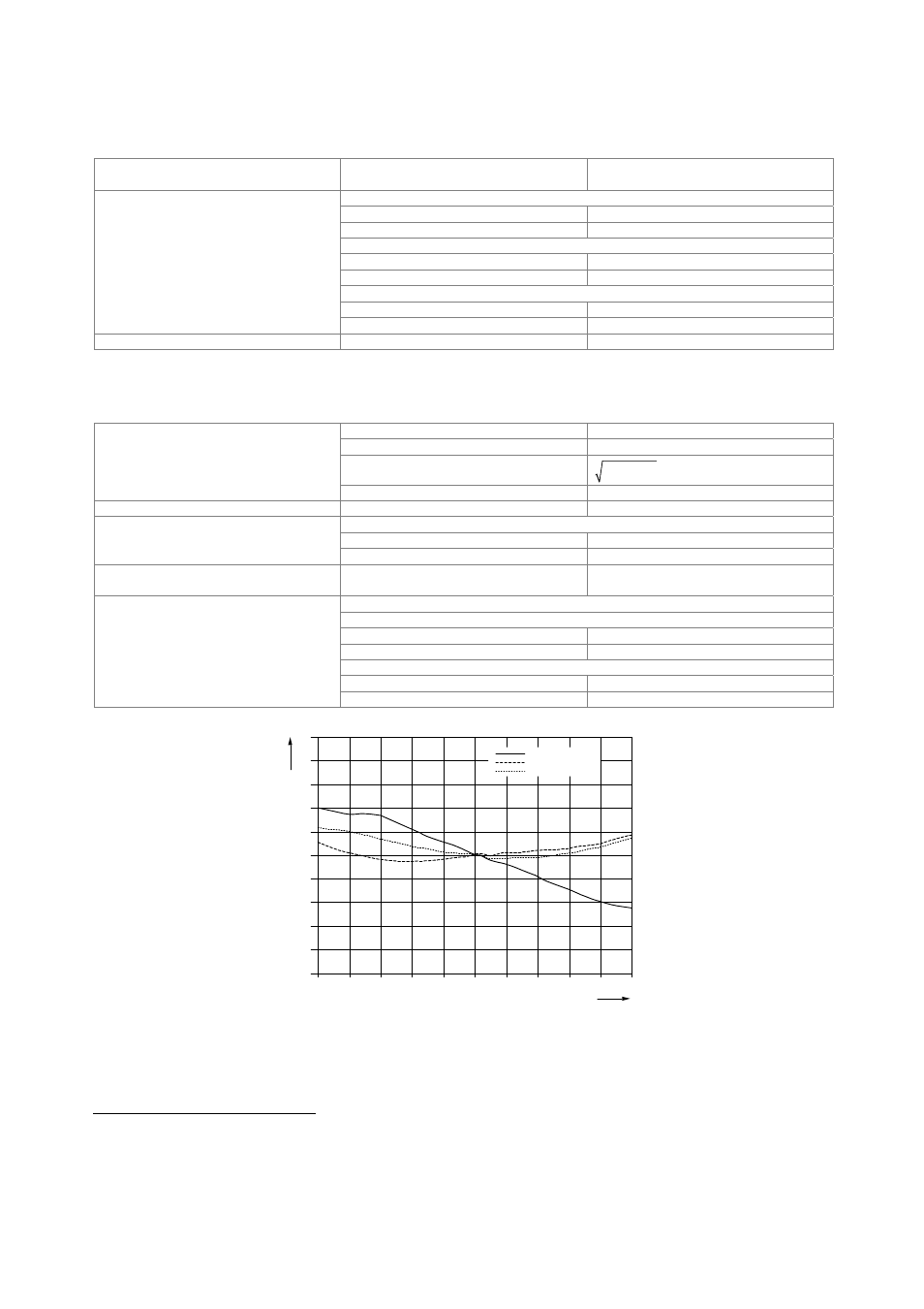
Measured frequency response of external wideband I/Q modulation.
3
Value applies after 1 hour warm-up time and recalibration for 4 hours of operation and temperature variations of less than +5 °C.