Differential i/q output (r&s, Smu-b16 option), Digital baseband output (r&s – Atec Rohde-Schwarz-SMU200A User Manual
Page 21: Smu-b18 option)
Version 08.00, January 2012
Rohde & Schwarz
R&S
®
SMU200A Vector Signal Generator
21
Differential I/Q output (R&S
®
SMU-B16 option)
One R&S
®
SMU-B16 option can be installed; the I/Q output signals are available either for path A or B.
This option is not compatible with rear-panel outputs (R&S
®
SMU-B81 and R&S
®
SMU-B82 options).
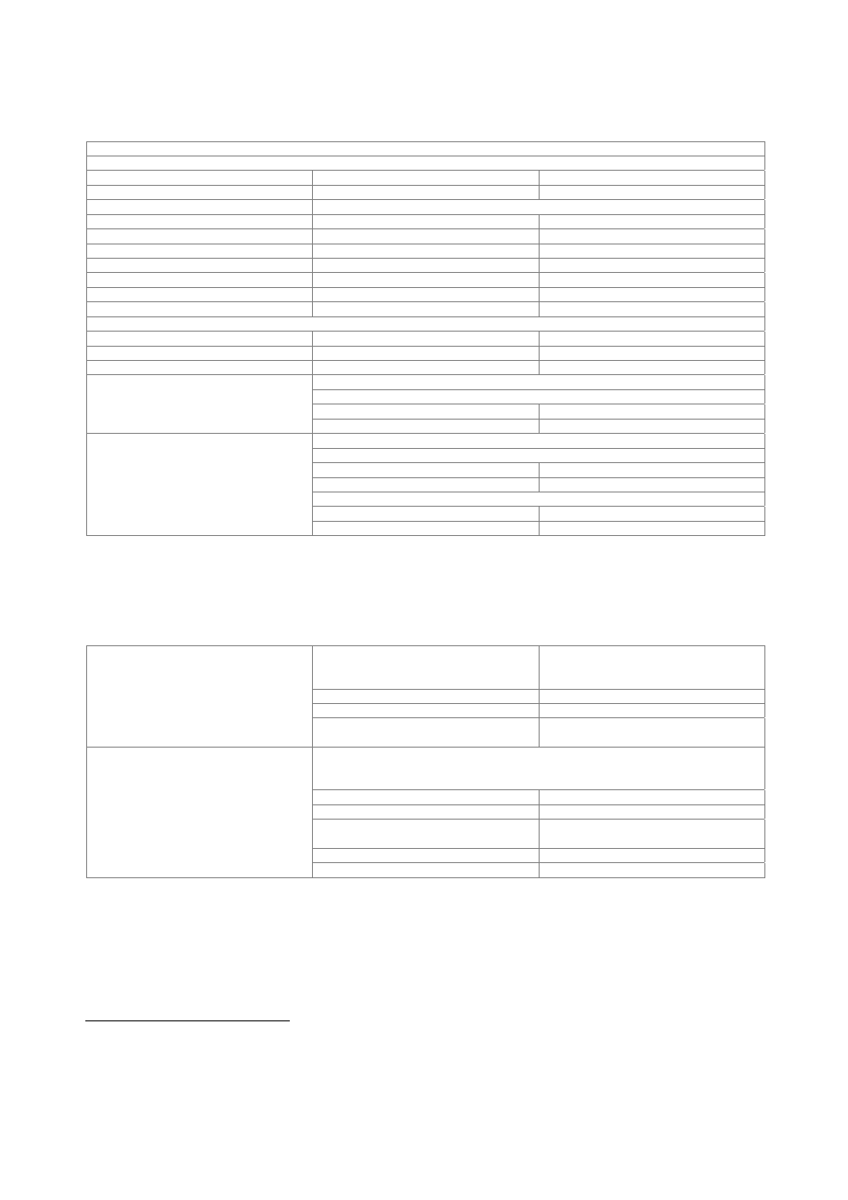
Additional specifications for I/Q outputs with R&S
®
SMU-B16 option
Output impedance
Single-ended
50
Ω
Differential
100
Ω
Output voltage
output voltage depends on set modulation signal
Single-ended
EMF
0.02 V to 2 V (V
p
)
Resolution
1
mV
Differential
EMF
0.04 V to 4 V (V
pp
)
Resolution
2
mV
Bias voltage (single-ended and differential) EMF
–3.6 V to +3.6 V
Resolution
2
mV
Uncertainty
1 % + 4 mV
Offset voltage
Differential
EMF
–300 mV to +300 mV
Resolution
0.2
mV
Uncertainty
1 % + 0.1 % × bias voltage + 1 mV
at R
L
= 50
Ω, output voltage > 0.5 V (V
p
)
magnitude
up to 10 MHz
< 0.2 dB, 0.05 dB (typ.)
Differential signal balance
up to 40 MHz
0.2 dB (typ.)
at R
L
= 50
Ω, output voltage > 0.5 V
(V
p
)
magnitude
up to 10 MHz
0.02 dB (typ.)
up to 40 MHz
0.03 dB (typ.)
nonlinear phase
up to 10 MHz
0.1° (typ.)
Frequency response
5
up to 30 MHz
0.2° (typ.)
Digital baseband output (R&S
®
SMU-B18 option)
The R&S
®
SMU-B18 option makes digital I/Q signals available on the rear panel of the instrument. The digital I/Q output can be used
for the lossless connection of the R&S
®
SMU200A to the digital I/Q input of other Rohde & Schwarz instruments (e.g. R&S
®
AMU200A
baseband signal generator and fading simulator). One R&S
®
SMU-B18 can be installed.
standard
in line with Rohde & Schwarz TVR290,
I/Q data and control signals, data and
interface clock
level LVDS
connector 26-pin
MDR
Interface
data rate
30 MHz to 100 MHz with 1 MHz resolution,
81.6 MHz
With source ‘user-defined’, the sample rate must be entered via the parameter ‘sample
rate’, no I/Q data clock being necessary. With source ‘digital I/Q out’ or ‘digital I/Q in’,
the sample rate will be estimated on the basis of the applied I/Q data clock.
source user-defined,
digital I/Q out, digital I/Q in
sample rate
400 Hz to 100 MHz
max. sample rate limited by actual
interface data rate
resolution (user-defined)
0.001 Hz
I/Q sample rate
frequency uncertainty (user-defined)
< 5 × 10
−
14
5
Optimize internal I/Q impairments for RF output switched off.