Level – Atec RohdeSchwarz-SMW200A User Manual
Page 8
Version 01.02, September 2013
8
Rohde & Schwarz R&S
®
SMW200A Vector Signal Generator
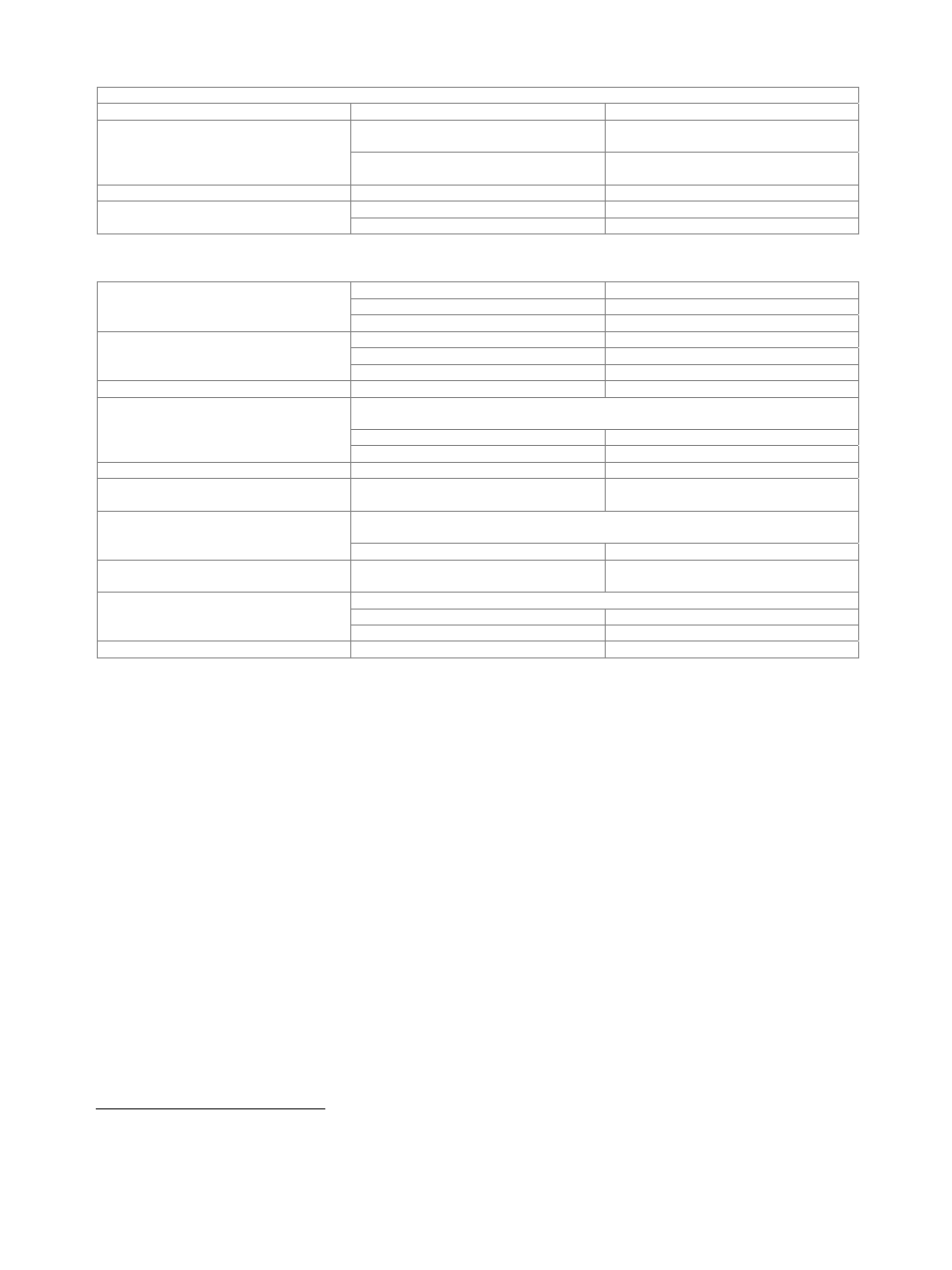
Input for electronic tuning of internal reference frequency
Connector type
EFC on rear panel
BNC female
Sensitivity
standard
0.5 × 10
–8
/V to 3 × 10
–8
/V,
1 × 10
–8
/V to 2 × 10
–8
/V (typ.)
with R&S
®
SMW-B22 option
5 × 10
–9
/V to 2 × 10
–8
/V,
8 × 10
–9
/V to 9.5 × 10
–9
/V (typ.)
Input voltage
–10 V to +10 V
Input impedance
standard
10 kΩ (nom.)
with R&S
®
SMW-B22 option
5 kΩ (nom.)
Level
Setting range
100 kHz ≤ f < 1 MHz
–145 dBm to +8 dBm
1 MHz ≤ f < 3 MHz
–145 dBm to +13 dBm
3 MHz ≤ f ≤ 6 GHz
–145 dBm to +30 dBm
Specified level range
100 kHz ≤ f < 1 MHz
–120 dBm to +3 dBm (PEP)
2
1 MHz ≤ f < 3 MHz
–120 dBm to +8 dBm (PEP)
2
3 MHz ≤ f ≤ 6 GHz
–120 dBm to +18 dBm (PEP)
2
Resolution of setting
0.01 dB (nom.)
Level error
level setting characteristic: auto,
temperature range from +18 °C to +33 °C
100 kHz < f ≤ 3 GHz
< 0.5 dB
3 GHz < f ≤ 6 GHz
< 0.7 dB
Additional level error
pulse modulation
< 0.5 dB
Output impedance
VSWR in 50 Ω system
level setting characteristic: auto
< 1.6
Setting time
3
to < 0.1 dB deviation from final value, with GUI update stopped, no relay switchover, f >
10 MHz
after IEC/IEEE bus delimiter
< 1 ms, 0.6 ms (typ.)
Interruption-free level setting range
level setting characteristic:
uninterrupted level setting
> 20 dB
Reverse power (from 50 Ω source)
maximum permissible RF power in output frequency range of RF path for f > 1 MHz
1 MHz < f ≤ 3 GHz
50 W
3 GHz < f ≤ 6 GHz
10 W
Maximum permissible DC voltage
50 V
2
PEP = peak envelope power.
3
Installation of software that is not authorized by Rohde & Schwarz for use on the R&S
®
SMW200A or installation of antivirus software can deteriorate
the setting time performance.