I/q modulation, I/q modulation performance – Atec RohdeSchwarz-SMW200A User Manual
Page 19
Version 01.02, September 2013
Rohde & Schwarz R&S
®
SMW200A Vector Signal Generator
19
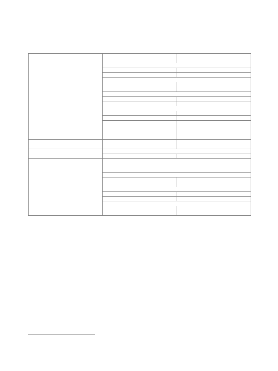
I/Q modulation
I/Q modulation performance
Operating modes
external wideband I/Q,
internal baseband I/Q
RF modulation bandwidth
with external wideband I/Q inputs, I/Q wideband on
1 MHz ≤ f ≤ 4 GHz
±25 % of carrier frequency
4 GHz < f
±1 GHz
with external wideband I/Q inputs, I/Q wideband off
f ≤ 1000 MHz
±10 % of carrier frequency
f > 1000 MHz
±100 MHz
with internal baseband I/Q, I/Q wideband on
1 MHz < f ≤ 320 MHz
±25 % of carrier frequency
f > 320 MHz
±80 MHz
RF frequency response in specified RF
modulation bandwidth
with external wideband I/Q inputs
I/Q wideband on
< 9 dB, < 6 dB (meas.)
I/Q wideband off
< 5 dB, < 3 dB (meas.)
with internal baseband I/Q, I/Q wideband
on, optimization mode high quality
< 1.0 dB, < 0.3 dB (meas.)
Carrier leakage
4
mode: internal baseband I/Q,
referenced to full-scale input
< –55 dBc
Suppression of image sideband for entire
instrument in modulation bandwidth
mode: internal baseband I/Q,
up to 80 MHz I/Q BW
> 50 dB, 60 dB (typ.)
Two-tone IMD (2 carriers)
PEP = 0 dBm
up to 80 MHz carrier spacing
< –40 dBc (typ.)
I/Q impairments (analog)
These impairments are set within the analog I/Q modulator section. They can be used
in external wideband I/Q mode and internal baseband I/Q mode. They cannot be
applied to the analog or digital I/Q outputs.
I offset, Q offset
setting range
–10 % to +10 %
resolution 0.01
%
gain imbalance
setting range
–1.0 dB to +1.0 dB
resolution 0.01
dB
quadrature offset
setting range
–10° to +10°
resolution 0.01°
4
Value applies after 1 hour warm-up time and recalibration for 4 hours of operation and temperature variations of less than +5 °C.