Fading and noise, Fading simulator (r&s, Smw-b14 option) – Atec RohdeSchwarz-SMW200A User Manual
Page 33
Version 01.02, September 2013
Rohde & Schwarz R&S
®
SMW200A Vector Signal Generator
33
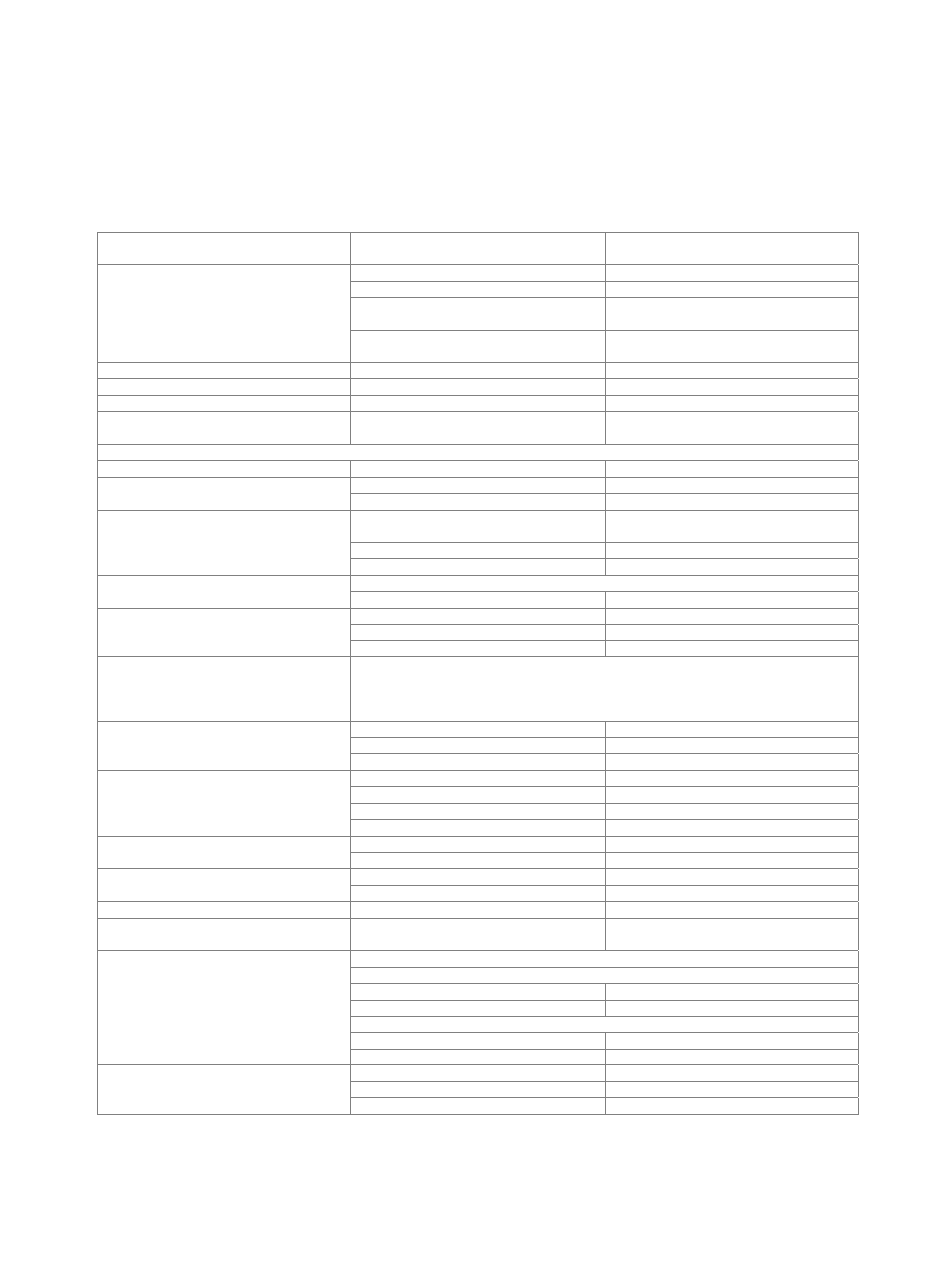
Fading and noise
Fading simulator (R&S
®
SMW-B14 option)
At least one R&S
®
SMW-B10 baseband generator must be installed.
All frequency and time settings are coupled to the internal reference frequency.
Number of installable fading simulator
modules
1, 2 or 4
Number of available fading channels
(“logical” faders)
one R&S
®
SMW-B14 installed
1
two or four R&S
®
SMW-B14 installed
2
with R&S
®
SMW-K74 option,
two R&S
®
SMW-B14 installed
up to 4
(see R&S
®
SMW-K74 specifications)
with R&S
®
SMW-K74 option,
four R&S
®
SMW-B14 installed
up to 16
(see R&S
®
SMW-K74 specifications)
Number of fading paths (per logical fader)
20
Bandwidth
up to 160 MHz
Start seed
0 to 9
Fading profiles
static path, pure Doppler, Rayleigh, Rice,
constant phase
Fading profile parameter
Rayleigh
pseudo-noise interval
> 1 year
Constant phase
phase
0° to 360°
phase resolution
1°
Pure Doppler
maximum resulting Doppler shift
frequency ratio × current Doppler
frequency
frequency ratio
–1 to +1
resolution 0.01
Rician
combination of Rayleigh and pure Doppler
power ratio
–30 dB to +30 dB
Fading path loss
setting range
0 dB to 50 dB
resolution 0.01
dB
accuracy
< 0.01 dB
Fading path delay
The 20 fading paths are divided in 4 path groups. Each group consists of 3 fine delay
and 2 standard delay paths. A basic delay can be set per path group and an additional
delay per path. The total delay per path is the sum of the basic delay of the respective
group and of the additional delay of the path.
Basic delay per group
group 1
0 s
group 2, 3, 4
0 s to 0.5 s
resolution 5
ns
Additional delay per path
fine delay path setting range
0 µs to 20 µs
fine delay path resolution
2.5 ps
standard delay path setting range
0 µs to 20 µs
standard delay path resolution
5 ns
Speed range
at f = 1 GHz
0 km/h to 4320 km/h
accuracy
< 0.1 %
Doppler frequency
setting range
0 Hz to 4000 Hz
accuracy
< 0.1 %
Restart
standard
auto, manual, external
Total insertion loss
automatic or user-definable, with clipping
indicator
0 dB to 18 dB
Correlation
fading paths in signal path A pairwise with fading paths in signal path B
correlation coefficient
setting range
0 % to 100 %
resolution 5
%
correlation phase
setting range
0° to 360°
resolution 1°
Lognormal
standard deviation
0 dB to 12 dB
resolution 1
dB
local constant at f = 1 GHz
20 m to 2000 m