Digital baseband inputs/outputs – Atec RohdeSchwarz-SMW200A User Manual
Page 23
Version 01.02, September 2013
Rohde & Schwarz R&S
®
SMW200A Vector Signal Generator
23
Digital baseband inputs/outputs
Depending on the installed software and hardware options, the R&S
®
SMW200A is able to receive digital baseband signals and to
output digital baseband signals. The digital I/Q input/output can be used for the lossless connection of the R&S
®
SMW200A to the
digital I/Q input/output of other Rohde & Schwarz instruments (for example the R&S
®
CMW500 radiocommunications tester in fading
applications).
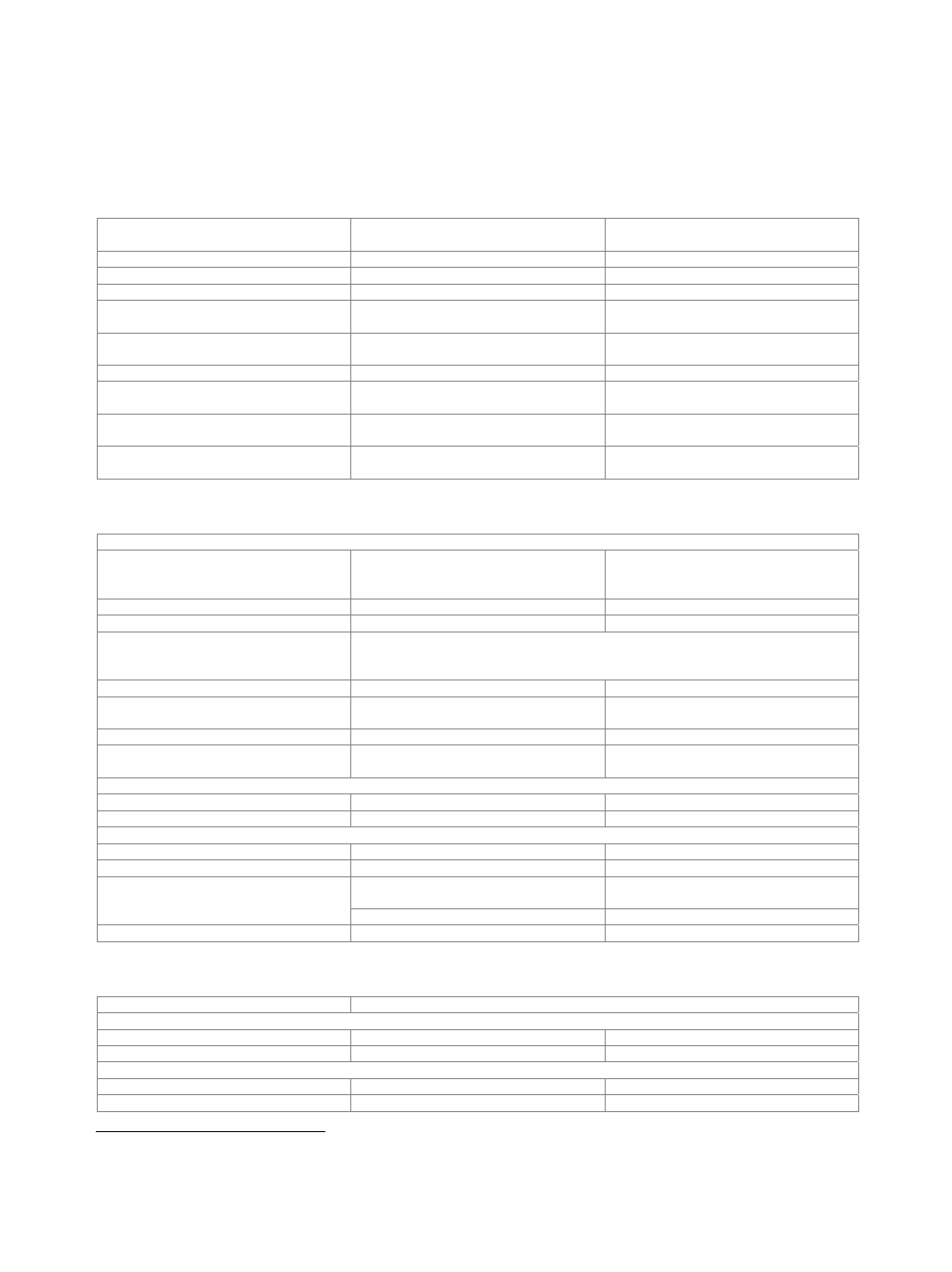
The following table gives an overview of which software and hardware options are required for which digital I/Q connectivity:
Digital I/Q inputs
Digital I/Q outputs
Minimum required R&S
®
SMW200A
options
– 1 R&S
®
SMW-B13 + 1 × R&S
®
SMW-K18
– 2 R&S
®
SMW-B13T + 2 × R&S
®
SMW-K18
1
–
1 × R&S
®
SMW-B10
1 1 1×
R&S
®
SMW-B10 + R&S
®
SMW-B13 +
1× R&S
®
SMW-K18
1
2
1 × R&S
®
SMW-B10 + R&S
®
SMW-B13T +
2 × R&S
®
SMW-K18
2
–
2 × R&S
®
SMW-B10
2
1
2 × R&S
®
SMW-B10 + R&S
®
SMW-B13 +
1 × R&S
®
SMW-K18
2
2
2 × R&S
®
SMW-B10 + R&S
®
SMW-B13T +
2 × R&S
®
SMW-K18
> 2 (max. 6, depending on MIMO mode)
> 2 (max. 6, depending on MIMO mode)
2 × R&S
®
SMW-B10 + 4 × R&S
®
SMW-B14
+ R&S
®
SMW-B13T + 2 × R&S
®
SMW-K18
Output parameters
Interface
Standard
in line with R&S
®
Digital I/Q Interface
9
,
I/Q data and control signals, data and
interface clock
Level
LVDS
Connector
26-pin
MDR
I/Q sample rate
With source ‘user-defined’, the sample rate must be entered via the parameter ‘sample
rate’, no I/Q data clock being necessary. With source ‘digital I/Q out’, the sample rate
will be estimated on the basis of the applied I/Q data clock.
Source
user-defined, digital I/Q out
Sample rate
max. sample rate depending on connected
receiving device
400 Hz to 200 MHz
Resolution (user-defined)
0.001 Hz
Frequency uncertainty (user-
defined)
< (5 × 10
−
14
+ relative deviation of
reference frequency) × sample rate (nom.)
I/Q data
Resolution
up to 18 bit
Logic format
two’s complement
Physical signal level
Setting range
0 to –60 dBFS
Resolution
0.01
dBFS
Bandwidth (RF)
sample rate = 200 MHz (no interpolation,
user-defined)
160 MHz
sample rate < 200 MHz (interpolation)
0.8 × sample rate
Control signals
markers
3
Input parameters
Input level
peak level
Peak level
Setting range
–60 dB to +3 dB, referenced to full scale
Resolution
0.01
dB
Crest factor
Setting range
0 dB to +30 dB
Resolution
0.01
dB
9
R&S
®
Digital I/Q Interface is a Rohde & Schwarz internal company standard for the transmission of digital I/Q data. It is supported by a wide range of
signal generators, signal analyzers and radiocommunications testers.