Internal baseband characteristics (r&s, Smw-b13 or r&s, Smw-b13t option) – Atec RohdeSchwarz-SMW200A User Manual
Page 21: Analog i/q outputs (r&s, Differential analog i/q outputs (r&s, Smw-k16 option)
Version 01.02, September 2013
Rohde & Schwarz R&S
®
SMW200A Vector Signal Generator
21
Internal baseband characteristics
(R&S
®
SMW-B13 or R&S
®
SMW-B13T option)
The R&S
®
SMW-B13 option provides one I/Q path to the RF section (to RF path A) as well as one analog I/Q output (i.e. one I and one
Q output connector). The R&S
®
SMW-B13T option provides two I/Q paths to the RF section (if two RF paths are installed) as well as
two analog I/Q outputs. With two RF paths, R&S
®
SMW-B13T is required.
Either R&S
®
SMW-B13 or R&S
®
SMW-B13T must be installed on the instrument.
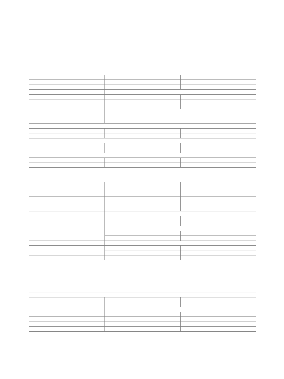
D/A converter
Data rate
200 MHz
Resolution
16
bit
Sampling rate
800 MHz (internal interpolation × 4)
Aliasing filter
with amplitude, group delay and S
i
correction
Bandwidth, rolloff to –0.1 dB
80 MHz
D/A converter interpolation spectra
up to 10 MHz
< –80 dBc
up to 80 MHz
< –73 dBc
I/Q impairments (digital baseband)
These impairments are set in the digital baseband section of the R&S
®
SMW200A. They
act on the I/Q signal sent to the I/Q modulator/RF section, as well as on the I/Q signals
at the analog or digital I/Q outputs (of the respective path)..
Carrier leakage
Setting range
–10 % to +10 %
Resolution
0.01
%
I
≠ Q (imbalance)
Setting range
–1 dB to +1 dB
Resolution
0.001
dB
Quadrature offset
Setting range
–10° to +10°
Resolution
0.01°
Analog I/Q outputs (R&S
®
SMW-B13 or R&S
®
SMW-B13T option)
Number of I/Q outputs
with R&S
®
SMW-B13 option
1
with R&S
®
SMW-B13T option
2
Output impedance
50 Ω
Output voltage
EMF (output voltage depends on set
modulation signal)
1 V (V
p
)
Offset
EMF
< 1 mV
Frequency response
5
at
R
L
= 50 Ω
Magnitude
up to 10 MHz
0.02 dB (meas.)
up to 80 MHz
0.03 dB (meas.)
I/Q balance
6
at
R
L
= 50 Ω
Magnitude
up to 10 MHz
0.01 dB (meas.)
up to 80 MHz
0.02 dB (meas.)
Spectral purity
at R
L
= 50 Ω
SFDR (sine)
up to 2 MHz
> 70 dB
up to 20 MHz
60 dB (meas.)
Wideband noise
10 MHz sine wave at 1 MHz offset
–155 dBc (typ.)
Differential analog I/Q outputs (R&S
®
SMW-K16 option)
This option can be installed once if the instrument is equipped with the R&S
®
SMW-B13 option. If the instrument is equipped with the
R&S
®
SMW-B13T option, differential analog I/Q outputs can be used either on signal path A or B with one R&S
®
SMW-K16 option. For
differential analog I/Q outputs to be used on signal paths A and B simultaneously, two R&S
®
SMW-K16 must be installed.
Output impedance
Single-ended
50
Ω
Differential
100
Ω
Output voltage
output voltage depends on set modulation signal
Single-ended
EMF
0.02 V to 2 V (V
p
)
Resolution
1
mV
Differential
EMF
0.04 V to 4 V (V
pp
)
Resolution
2
mV
5
“Optimize internal I/Q impairments for RF output” switched off.
6
Value applies after 1 hour warm-up time and recalibration for 4 hours of operation and temperature variations of less than +5 °C.