Atec Agilent-N5230A User Manual
Page 15
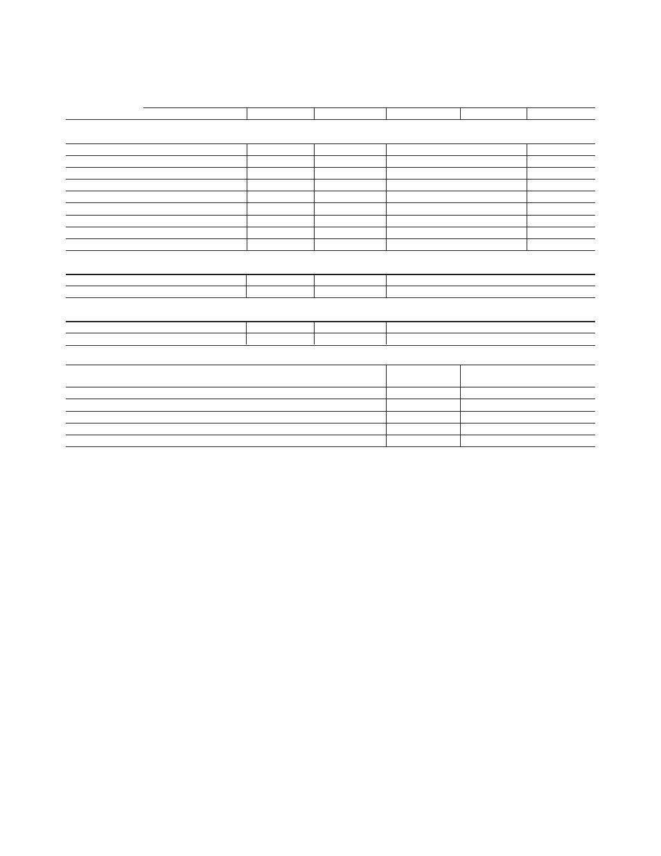
Table 7. Test port input (Continued)
Description
Specifications
Typicals
Options 140, 240 Options 145, 245 Options 146, 246
Options 140, 240 Options 145, 245 Options 146, 246
Stability phase
Stability as defined as a ratio measurement made at the test port.
300 kHz to 10 MHz
±0.360°/°C
±0.360°/°C
10 to 45 MHz
±0.020°/°C
±0.020°/°C
45 to 500 MHz
±0.030°/°C
±0.030°/°C
500 MHz to 2 GHz
±0.050°/°C
±0.070°/°C
2 to 4 GHz
±0.100°/°C
±0.150°/°C
4 to 8 GHz
±0.150°/°C
±0.250°/°C
8 to 13.5 GHz
±0.300°/°C
±0.500°/°C
13.5 to 16 GHz
±0.300°/°C
±0.500°/°C
16 to 20 GHz
±0.350°/°C
±0.650°/°C
Reference level magnitude
Range
±200 dB
±200 dB
±200 dB
Resolution
.001 dB
.001 dB
.001 dB
Reference level phase
Range ±500°
±500°
±500°
Resolution
.01°
.01°
.01°
Damage input level
Test port 1, 2, 3, and 4
+27 dBm
+27 dBm or ±16 VDC
or ±16 VDC
Receivers R, A, B, C, D
+15 dBm or ±16 VDC
Source out (reference)
+27 dBm or ±16 VDC
Source out (test ports)
+27 dBm or ±16 VDC
Coupler thru
+27 dBm or ±16 VDC
Coupler arm
+15 dBm or ±0 VDC
15