Atec Agilent-8722ES User Manual
Page 5
9
Agilent 8719ES, 8720ES, and 8722ES Option 007
Agilent 8719ES, 8720ES, and 8722ES Option 085
Includes instruments with Options 012
1
and/or 089.
Option 007 replaces the standard solid-state
transfer switch with a mechanical switch to pro-
vide higher output power.
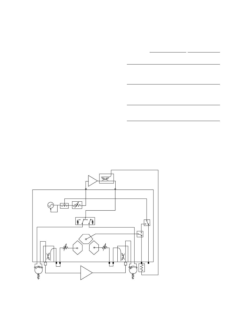
Option 085 adds internally controlled 0 to 55 dB
step attenuators (5 dB steps) in the receiver path
of both ports, an RF loop that allows the addition
of an amplifier before the transfer switch, and RF
loops after the switch that allow insertion of isola-
tors, required for measurements above 1 watt. An
internal reference channel switch is added and inter-
nal bias tees are deleted. This system is capable of
full two-port calibrated measurements to 20 watts.
Measurements up to 100 watts may be possible
using specific configurations. Option 085 includes
direct sampler access (Option 012). Option 085 is
not compatible with Option 400.
System dynamic range
Option 007
Option 085
Frequency
range (GHz)
8719ES/20ES 8722ES
8719D/20ES
8722ES
0.05 to 0.84
82 dB
72 dB
82 dB
72 dB
0.84 to 8
105 dB
98 dB
105 dB
98 dB
8 to 20
105 dB
96 dB
105 dB
96 dB
20 to 40
—
85 dB
—
82 dB
Maximum output power
Option 007
Option 085
2
8719ES/8720ES
+10 dBm
+5 dBm
8722ES (0.05 to 20 GHz)
0 dBm
–5 dBm
8722ES (20 to 40 GHz)
–5 dBm
–10 dBm
Supplemental characteristics (Option 085)
Maximum R-channel input level: 0 dBm
Minimum R-channel input level: –34 dBm
Maximum RF port input: +43 dBm
Attenuators: 55 dB maximum, 5 dB steps
Maximum test port power (no isolators): +30 dBm
Maximum test port power (with high power
isolators): +43 dBm
Mechanical
Transfer
switch
Source
B
R
A
Samplers
RF out
RF in
+43 dBm max
Customer supplied
booster amplifier
and coupler
Amplifier under test
R channel input
0 dBm max
+43 dBm max input
(20 watts)
+43 dBm max output
(20 watts)
Customer supplied isolation
(for output above +30 dBm)
-55 dB
-55 dB
R out
Reference
Signal
Switches
Option 085 block diagram and example
high power measurement setup
1. Internal test set not bypassed.
2. With jumper cable installed between RF out and RF in ports: that is, no external amplification.