Digital i/o and sync port pinouts – Antex Electronics StudioCard AV Pro, StudioCard 2000, & SC-22 User Manual
Page 145
A p p e n d i x B
B-6 Antex StudioCard
Copyright © 1997
Digital I/O and
Sync Port
Pinouts
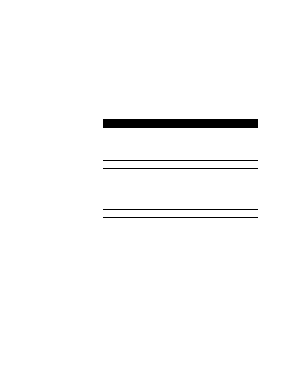
The pinout for the digital I/O port is shown in the table below.
All ground pins are wired to the computer’s chassis ground.
Pin
Description
1
External clock input
2
Digital audio output (+)
3
MIDI output (+)
4
MIDI input (+)
5
SMPTE (LTC) input (+)
6 Ground
7
Digital audio input (+)
8 Ground
9
MIDI output (-)
10 Ground
11
Digital audio input (-)
12
Digital audio output (-)
13
SMPTE (LTC) output
14
MIDI input (-)
15
SMPTE (LTC) input (-)