Maintenance, Inverter fan replacement, 8 maintenance – Alpha Technologies INEX Inverter System User Manual
Page 41: 1 inverter fan replacement
Argus Technologies Ltd.
014-114-C0 Rev D WC
Printed in Canada. © 2008 Argus Technologies Ltd. ARGUS and INEX are registered trademarks of Argus Technologies Ltd. All Rights Reserved.
Page 31 of 43
8 Maintenance
Although very little maintenance is required with INEX systems, routine checks and adjustments by qualified
service personnel are recommended to ensure optimum system performance.
The following table lists the maintenance procedures for this system. These procedures should be performed at
least twice a year.
WARNING: HIGH VOLTAGE AND SHOCK HAZARD.
Use extreme care when working inside the shelf while the system is energized.
Do not make contact with live components or parts.
Circuit cards, including RAM chips, can be damaged by static electricity. Always wear a grounded
wrist strap when handling or installing circuit cards.
Procedure
Date Completed
Clean ventilation openings
Inspect all system connections (re-torque as necessary)
Verify alarm/control settings
Verify alarm relay operation
Table P–Sample maintenance log
8.1
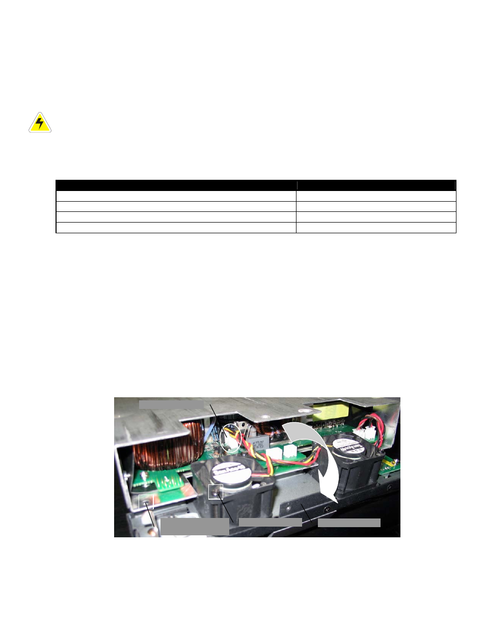
Inverter Fan Replacement
1. Unlock the inverter and slide the module 10 cm (4”) out of the shelf. Wait two minutes for module capacitors
to discharge.
2. Remove the six (6) screws that secure the front cover to the module.
3. Gently slide the front cover (with the fans) out of the module case.
4. Disconnect the fan power connectors (one per fan).
5. Note the direction of airflow and remove the fans from the assembly.
6. Install the replacement fans following the preceding steps in reverse order.
Front cover w/fans
Fan power connectors
Fan screw (2 per fan)
Screw hole (6 places)
for front panel