Sts/controller shelf, 6 sts/controller shelf – Alpha Technologies INEX Inverter System User Manual
Page 24
Argus Technologies Ltd.
014-114-C0 Rev D WC
Printed in Canada. © 2008 Argus Technologies Ltd. ARGUS and INEX are registered trademarks of Argus Technologies Ltd. All Rights Reserved.
Page 14 of 43
4.6 STS/Controller
Shelf
WARNING
Ensure all power sources are OFF during wiring. Disconnect battery cables from battery.
1. Follow wiring instructions to suit your installation.
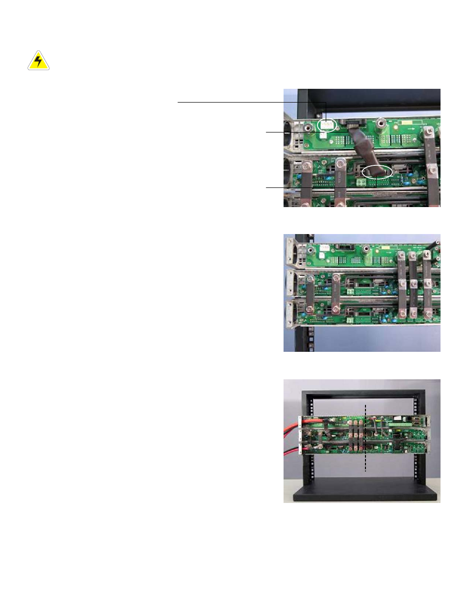
2. Locate the CN2 connector on the backplane of the STS shelf
and the CN7 connector on the backplane of the inverter
shelf. Connect these two connectors with the attached STS
signal cable as shown:
3. Connect AC bus connectors of STS shelf to the AC bus of
the top level inverter shelf.
4. Then connect the AC bus connectors between inverter
shelves.
NOTE:
Spacers supplied are required on the last (bottom) shelf for AC
bars.
5. Route both DC input wires through the wire hole on the left
side of the inverter shelf. Use the cross-pan type nickel
screws in accessory kit for fixing both DC input wires.
CAUTION
To connect AC output wires onto the system,
only one AC line and AC neutral are necessary to
be connected either from STS shelf or inverter
shelf.
6. For inverter shelf only or without STS module:
Connect AC LINE to the UC4 (AC-L OUT) connector of STS
shelf.
Connect AC NEUTRAL LINE onto UC3 (AC-N) connector of
STS shelf.
7. With STS module:
Connect AC LINE IN to UC5 and AC LINE OUT to UC4 of STS shelf. Connect AC NEUTRAL IN/OUT to UC3.
CN2: SYNC port on the
controller/interface shelf
backplane
CN7: SYNC port on the
inverter shelf
backplane
CN1: Use shorting plug
for pins 1 to 4 when
MBS is not installed
This page Next page