Shelf installation, Inverter shelf preparation/mounting, 3 shelf installation – Alpha Technologies INEX Inverter System User Manual
Page 14: 1 inverter shelf preparation/mounting
Argus Technologies Ltd.
014-114-C0 Rev D WC
Printed in Canada. © 2008 Argus Technologies Ltd. ARGUS and INEX are registered trademarks of Argus Technologies Ltd. All Rights Reserved.
Page 4 of 43
3 Shelf
Installation
This chapter is provided for qualified personnel to install the product.
3.1
Inverter Shelf Preparation/Mounting
The inverter shelf has been designed for flush or mid-mounting in a 19” relay rack. Mounting brackets are also
supplied for mounting in a 23” rack.
NOTE:
The shelf shall be mounted in a clean and dry environment. Allow at least 1.75” of free space in front of the unit
for unrestricted cooling airflow.
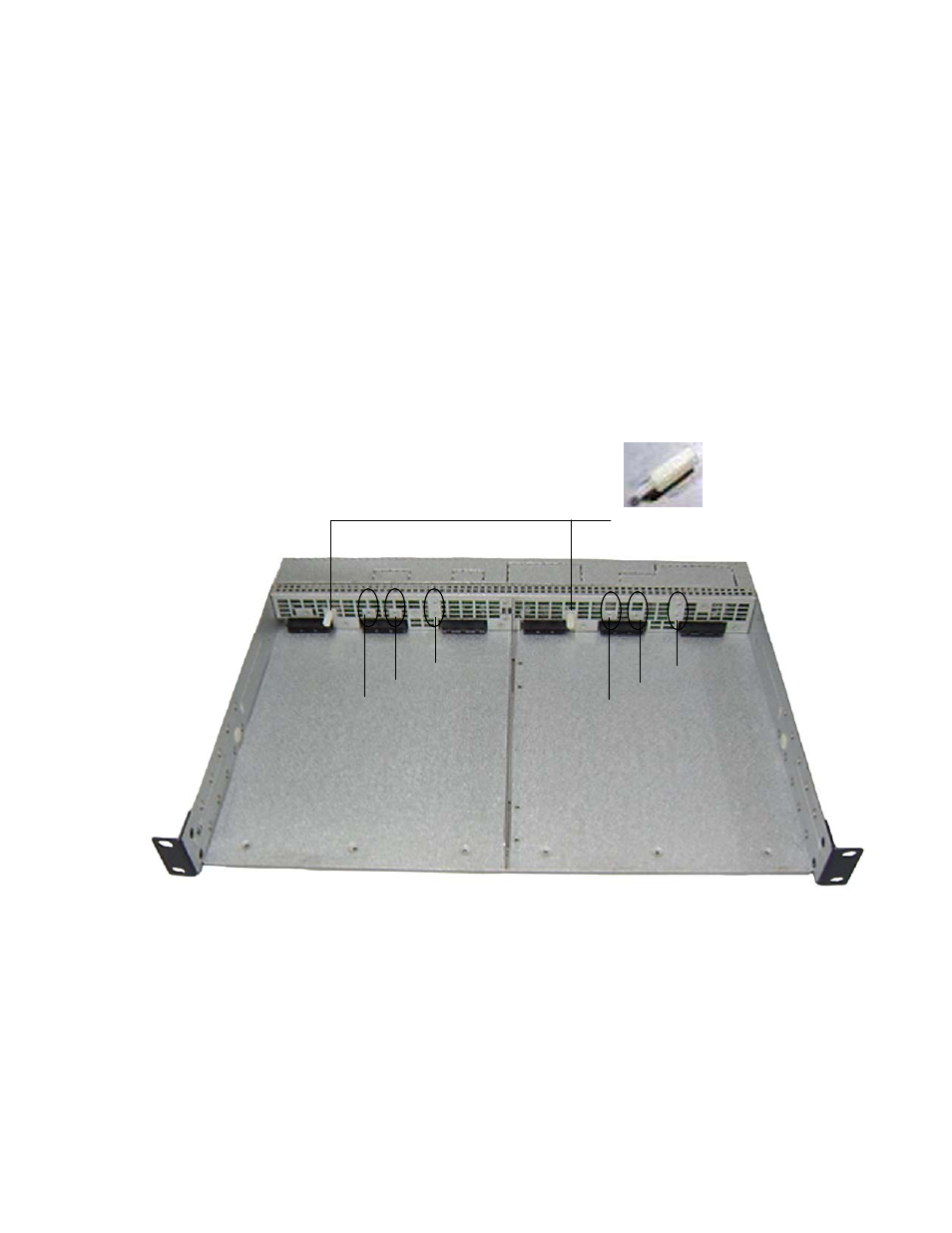
1. There are four holes right above three deck connectors of each inverter slot. Based on inverter model, insert
the supplied nylon guide pin to the corresponding hole:
• Position A for INV-4815A (as shown below)
• Position B for INV-4815EA
• Position C for INV-4810A
• Position D for INV-4810EA
CAUTION
System will fail to operate normally when inverter modules of different specifications are inserted
into inverter shelves. Use supplied nylon guide pins for securing only inverter modules of the
same specifications.
Nylon guide pins shown in Position A
B
C
D
B
C
D