Single inverter shelf system, 4 single inverter shelf system – Alpha Technologies INEX Inverter System User Manual
Page 19
Argus Technologies Ltd.
014-114-C0 Rev D WC
Printed in Canada. © 2008 Argus Technologies Ltd. ARGUS and INEX are registered trademarks of Argus Technologies Ltd. All Rights Reserved.
Page 9 of 43
NOTE:
Use the following table as a guide only. Ensure that the installation complies with the specific wiring rules
applicable to your country or area of jurisdiction.
Shelf number of
2 x 1000VA
inverter
cascaded
Input Current
Maximum
@ 40Vdc
110Vac Output
Current Max.
230Vac Output
Current Max.
Minimum Size
of DC Input
Wire Max.
Min. Size of
110Vac Output
Wire Max.
Min. Size of
230Vac Output
Wire Max.
#1
45.5A
18.2A
8.7A
#8 AWG
#14 AWG
#16 AWG
#2
91.0A
36.4A
17.4A
#4 AWG
#10 AWG
#14 AWG
#3
54.5A
26.1A
#8
AWG
#10
AWG
#4
72.7A
34.8A
#6
AWG
#10
AWG
#5
90.9A
43.5A
#4
AWG
#8
AWG
#6
109.1A
52.2A
#3
AWG
#8
AWG
Shelf number of
2 x 1500VA
inverter
cascaded
Input Current
Maximum
@ 40Vdc
110Vac Output
Current Max.
230Vac Output
Current Max.
Minimum Size
of DC Input
Wire Max.
Min. Size of
110Vac Output
Wire Max.
Min. Size of
230Vac Output
Wire Max.
#1
68.2A
27.3A
13.0A
#6 AWG
#12 AWG
#16 AWG
#2
136.4A
54.5A
26.1A
#2 AWG
#8 AWG
#12 AWG
#3
81.8A
39.1A
#6
AWG
#10
AWG
#4
109.1A
52.2A
#3
AWG
#8
AWG
#5
136.4A
65.2A
#2
AWG
#6
AWG
#6
163.6A
78.3A
#2
AWG
#6
AWG
Table A–Recommended wire size versus current
Remarks: 1. Total Power Rating (VA, W) = No. of shelf × Inverter module power rating (VA, W) * 2
2. I/P current = Total power rating (W) ч 0.88 ч 40
3. O/P current = Total power rating (VA) ÷ AC voltage
4.4
Single Inverter Shelf System
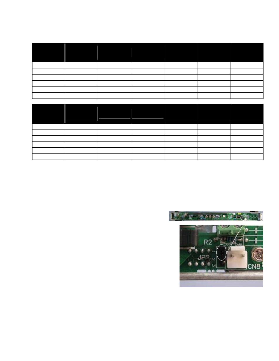
1. In the inverter shelf package, you will find a jumper.
When only ONE inverter shelf is applied in the system, insert
the jumper to pins 1 and 2 of connector JP2:
2. Negative (BAT-) and positive (BAT+) DC input terminal studs are located in the left side of backplane. In
consideration of the power rating and distance from the battery, choose appropriate gauge wire using Table A
as well as local wiring rules.
NOTE:
For inverter systems without a controller, open collector terminals are available on the inverter shelf backplane for
the inverter fail alarm. See details under point 9 of Section 4.5.