Alpha Technologies FXM 650, 1100, 2000 UPS User Manual
Page 10
017-230-B4 Rev B
8
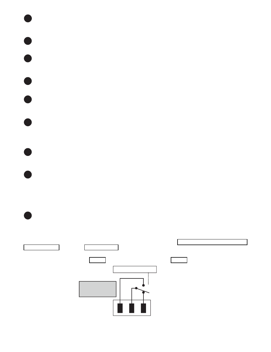
Figure 2 — Contact Layout (Standard for C1 to C5, Factory Option for C6)
Battery breaker
This circuit breaker provides over-current protection and is used as an on/off switch for the battery power. It must
be switched on for proper Alpha FXM operation.
2
Battery connector
The battery connector connects the external batteries to the Alpha FXM.
3
Replaceable fan assembly
This microprocessor-controlled fan turns on at a programmable temperature to lower the Alpha FXM internal tem-
perature. It must not be blocked. An Alarm is generated if the fan fails; a failed fan can be replaced in the field.
4
RJ45 communication module connector
The RJ-45 connector is the Alpha FXM Ethernet connector.
5
LCD control panel and menu navigation buttons
The LCD control panel together with the cancel, scroll and select buttons are used to monitor and control the
Alpha FXM.
6
Battery voltage test points
These test points accept 2 mm diameter test probe tips. The battery circuit breaker must be on to measure the
voltage.
The battery voltage test points are not to be used as a power outlet.
7
RS-232
This DE-9 connector allows a straight-through DE-9 to DE-9 connector cable to be used to connect the
Alpha FXM to a computer for remote control and monitoring.
8
Battery temperature sensor connector
The battery charging voltage is temperature dependant when compensation is not set to 0 mV/°C/cell. A battery
temperature sensor connects to the Alpha FXM so the Alpha FXM microprocessor can adjust the charging volt-
age for optimum charging. Refer to "UPS Maintenance > Battery" on page 38.
The sensor MUST be attached to the Alpha FXM for normal operation. If the sensor is not attached, a “Tempera-
ture Probe Unplugged” alarm appears on the LCD.
9
Contacts C1 to C6
Contacts C1 to C5 allow the Alpha FXM to be connected to an external monitoring panel or to traffic control
equipment.
The factory default settings can be reprogrammed to meet your requirements. Each contact can only be pro-
grammed for one function at a time and cannot show multiple conditions. See "UPS Maintenance > Relay & Load
Shed" on page 41 and section 6.5.7 on page 66 for the HyperTerminal interface.
For Contact C6, the default factory configuration is +48 Vdc output (FXM 650-24 is +24 Vdc), but it can be fac-
tory configured as a dry contact. Figure 2 shows the contact’s layout while Figure 3 shows the +48 Vdc or +24
Vdc terminal block layout.
The contacts have
a maximum rating
of 1A at 250V.
Microprocessor
UPS
Interior
Normally
Closed (NC)
Normally
Open (NO)
Common (C)
1