Installation and operation, Installing the powercage fox 3g hd-sdi, Rear panel connections and settings – Extron Electronics PowerCage FOX 3G HD-SDI User Guide User Manual
Page 13
Installation and
Operation
This section describes the installation and operation of the PowerCage FOX 3G HD-SDI,
including the following topics:
z
Installing the PowerCage FOX 3G HD-SDI
z
Rear Panel Connections and Indicators
z
PowerCage 1600 Front Panel Port, Control, and Indicators
z
WARNING: Installation and service must be performed by authorized personnel only.
Installing the PowerCage FOX 3G HD-SDI
The PowerCage FOX 3G transceiver is installed in an Extron PowerCage enclosure.
See “
Installing the FOX 3G HD-SDI Board in the PowerCage Enclosure
” in the
“Reference Information” section for the procedure.
Rear Panel Connections and Settings
Tx
Rx
HD/SDI INPUT
HD/SDI OUTPUTS
MODE
P
o
w
er
C
ag
e
FO
X 3G HD-SDI
1
2
4
3
5
1
2
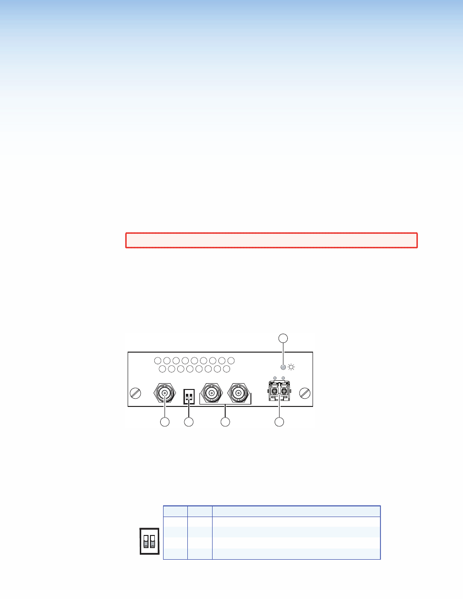
Figure 4.
PowerCage FOX 3G HD-SDI Transceiver Rear Panel
a
HD-SDI Input connector — If the PowerCage FOX 3G HD-SDI is configured as either
a bidirectional transceiver or as a transmitter, connect an HD-SDI, SDI, or 3G-SDI video
source to this BNC connector.
b
Mode switches — Set these DIP switches to the positions shown in the table below
to select the transceiver configuration.
SW2
Mode
Down
Up
Down Bidirectional transceiver (default position)
Up
Down
Transmitter with local monitor outputs
Receiver with daisy chaining
Spare (functions as a receiver with daisy chaining)
Up
Up
Down
SW1
MODE
1 2
PowerCage Fox 3G HD-SDI • Installation
7