Installation overview, Installation, Computer input select audio – Extron Electronics HSA 822M User’s Manual User Manual
Page 8
HSA 822M • Installation
HSA 822M • Installation
Installation
2-3
11
Connect power cords and turn on the devices that connect
to the surface access enclosure.
Mounting
Surface
Clamshell
Full Thread
Mounting Bolts
AAP Cables
Flat Washer
Power Cord
RJ-45 Connectors
Control and Status
Connector
Network (TP)
Cables
COMPUTER
INPUT
SELECT
AUDIO
HSA 822
Enclosure
Yellow Shipping
Restraints
REMOVE
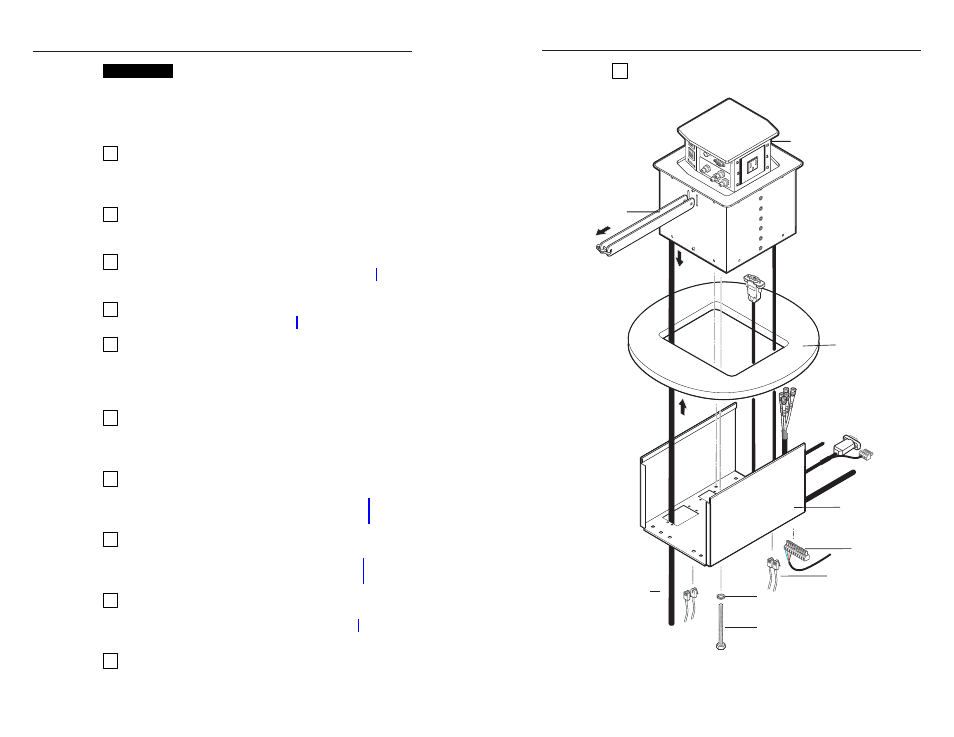
Figure 2-1 — Mounting the HSA 822M enclosure
CAUTION
Installation and service must be performed by
authorized personnel only.
Installation Overview
See figure 2-1 and the following steps to install the HSA 822M:
1
If desired, install the optional RJ-45 to RJ-11 conversion
kit(s) to replace one or more RJ-45 connectors with RJ-11
connectors. Refer to the RJ-45 to RJ-11 Conversion Kit
manual.
2
If desired, install the optional flexible conduit kit to
replace the removable AC power cord. Refer to the
Flexible Conduit Kit manual.
3
If you have an unprepared mounting template, prepare
the template. See “Preparing the Routing Template” on
page 2-4.
4
Cut a hole in the surface where the enclosure will be
installed. See “Preparing the Table” on page 2-5.
5
Run all cables necessary to support the AC, control and
status, and RJ-45 connectors and all planned AAP
connectors. Leave enough slack in the cables to connect
them to the underside of the enclosure or to the rear of the
AAPs before the AAPs are installed in the enclosure.
6
Turn off all of the equipment to be connected. Ensure that
the equipment connected to the RJ-45 connectors and the
connections for any AAPs are all turned off and
disconnected from the power source.
7
If applicable, connect cables to the rear connectors on the
AAPs to be installed in the HSA 822M. Install the desired
AAPs on the AAP/RJ-45 panel. See “Cabling and
Installing the AAPs” on page 2-7.
8
Route and secure the AAP cables inside the enclosure,
install the clamshell, and then secure the AAP cables to
the clamshell. See “Routing the AAP Cables and
Installing the Clamshell” on page 2-9.
9
Connect the power, RJ-45, and control and status cables to
the underside of the enclosure. Remove the yellow
shipping restraints. See “Cabling the Enclosure” on
page 2-11.
10
If not already accomplished, peel the protective coating
from the top surface and remove rubber strip that protects
the top surface’s flanged edges.
2-2