Installation, cont’d – Extron Electronics HSA 822M User’s Manual User Manual
Page 11
HSA 822M • Installation
HSA 822M • Installation
Installation, cont’d
2-8
Ensure that the edges of the AAP/RJ-45 panels do not
scratch the finished surface of the top panel flange when
removing the panels.
2
.
Cable the rear of the AAPs before fastening the AAPs to
the AAP/RJ-45 panel. Route the cables through the hole in
the underside of the surface mount enclosure and connect
them to the rear of the AAPs. If applicable, refer to the
cabling information in the documentation for the AAP.
3
.
Insert each of the AAP’s screws through the holes in the
AAP opening of the HSA AAP/RJ-45 panel. Secure each
AAP to the panel with the provided captive washers and
#4-40 nuts (figure 2-5).
#4-40 Nut w/ Captive
Washer
Cable
AAP/RJ-45
Panel
HS
A 822M
RGB 580xi SI AAP
CO
MPU
TER
INP
UT
SEL
ECT
AU
DIO
Figure 2-5 — Mounting an AAP on the AAP/RJ-45
panel
4
.
Replace the AAP/RJ-45 panel in the surface mount
enclosure and secure it in place with the screws removed
in step 1. If you lose an AAP/RJ-45 panel screw, four
spare screws are stored in the underside of the enclosure
(figure 2-8 on page 2-10, item
5
).
Routing the AAP Cables and
Installing the Clamshell
The AAP cables must have freedom of movement to permit
opening and closing the surface mount enclosure. At the same
time, they need to be restrained to prevent them from rubbing
against the edges of the enclosure cable access hole in the
underside of the surface mount enclosure. Rubbing against the
cable access hole edges can damage the cables. Route and
secure the AAP cables as follows:
1
.
Manually open the top panel to extend the AAP cables to
their maximum pull.
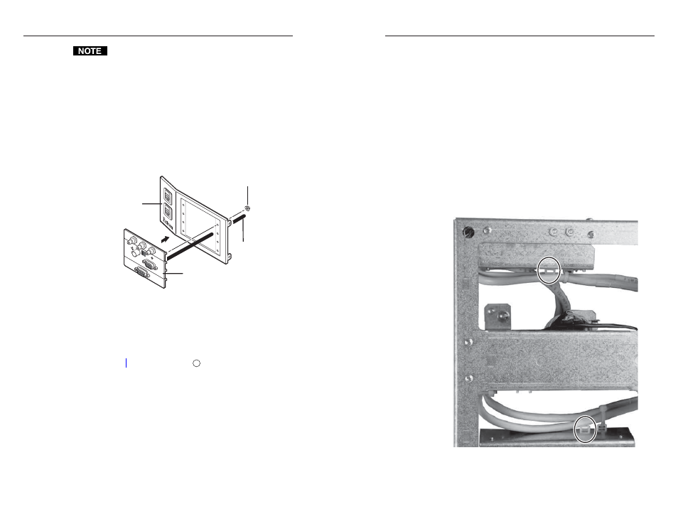
2
.
To prevent wear and tear or binding of the mechanism
caused by cable movement, secure the AAP cables inside
the enclosure. Use tie wraps to secure the cables to the tie-
downs accessible through the cable access holes
(figure 2-6).
Figure 2-6 — Cable tie-downs inside the HSA
(seen from underneath)
2-9