Level stop point and, Maintenance and modifications, cont’d – Extron Electronics HSA 822M User’s Manual User Manual
Page 21
Maintenance and Modifications, cont’d
HSA 822M • Maintenance and Modifications
HSA 822M • Maintenance and Modifications
Upper Limit
Switch
(Hidden)
Switch
Actuator
Upper Limit
Lock Nut
Upper Limit
Set Screw
5
.
Loosen the upper limit
lock nut.
6
.
Rotate the upper limit
set screw:
Clockwise
(tighten) to
lower the upper limit
of platform motion.
Counterclockwise
(loosen)
to raise the upper limit of
platform motion.
Adjustments do not take effect immediately. You must
use the motor mechanism to lower and raise the platform
to see the effect of your adjustment.
7
.
Lower and raise the platform to check the adjusted height.
If necessary, repeat step 6.
8
.
Tighten the upper limit lock nut.
9
.
Disconnect the power and control and status connectors.
10
.
Setting the Lower Limit Switch
(Lowered Platform Height)
This switch’s position is properly set in the factory.
The lower limit switch sets the stop point for the lowered
platform. If the switch is set too high or low, the retracted
platform is not flush with the surrounding flange. Set the
retracted height of the platform as follows:
1
.
Remove the surface mount enclosure from the table. See
“Removing and Replacing the Enclosure”, steps 1 through
12
. Place the enclosure on a horizontal surface. To protect
the finish, place the enclosure on a soft cloth. Let the AC
and control and status connectors (figure 3-1 on page 3-2,
items
7
and
9
) overhang the edge of the surface so that
they are accessible.
2
.
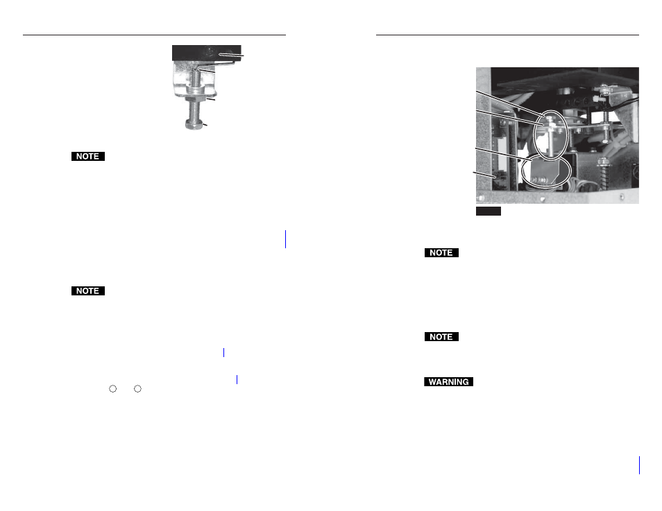
Locate the lower limit switch assembly (figure 3-8) inside
the enclosure.
Lower Limit
Set Screw
Control
Board
NOTE
RJ-45 connectors are removed for visibility.
Lower Limit
Switch
Lower Limit
Lock Nut
Figure 3-8 — Location of lower limit switch assembly
(seen from the side)
The lower limit switch looks similar to, but not exactly
like the upper limit switch shown on page 3-12.
3
.
Loosen the lower limit lock nut.
4
.
Rotate the lower limit set screw:
Clockwise
to raise the stop point of the retracted platform.
Counterclockwise
to lower the stop point of the retracted
platform.
Adjustments do not take effect immediately. You must
use the motor mechanism to raise and lower the platform
to see the effect of your adjustment.
5
.
Plug in AC power and the control and status device.
Do not reach tools or your hands into the area
behind the AC connectors or into the vicinity of the
power supply.
6
.
Raise and lower the platform to check the adjusted height.
If necessary, unplug power and repeat step 4.
7
.
Tighten the lower limit lock nut.
8
.
Disconnect the power and control and status connectors.
9
.
3-13
3-12