Cabling and installing the aaps, Installation, cont’d, Hsa 822 – Extron Electronics HSA 822M User’s Manual User Manual
Page 10
HSA 822M • Installation
HSA 822M • Installation
Installation, cont’d
2-6
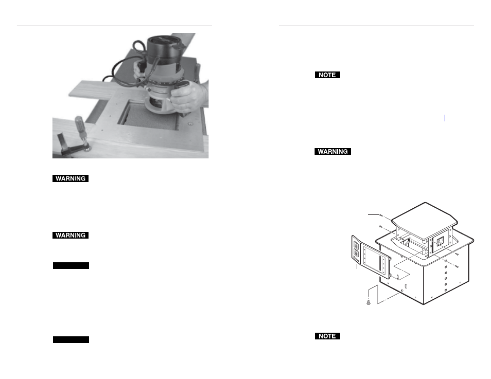
Figure 2-3 — Cutting the opening with a router
Wear safety glasses when operating the router.
Failure to heed this warning can result in eye injury.
4
.
Using a router with a 5/8" (or 16 mm) outside diameter
guide bushing and a 1/2" (or 12 mm or 12.7 mm) diameter
straight router bit, carefully cut the opening in the table
surface (figure 2-3).
5
.
Remove the C-clamps and the routing template.
The flanged edges of the top of the surface enclosure
are sharp when the HSA is not installed in a table.
Exercise caution when handling to prevent personal
injury.
CAUTION
The flanged edges of the top of the surface enclosure
are bevelled to an ultra-fine thickness of less than
0.04 (4/100)" (approximately 1 mm). These edges
are soft and can be easily nicked or bent. Exercise
caution when handling and mounting the
enclosure. Mishandling can damage the appearance
of the enclosure.
6
.
Remove the rubber strip that protects the top surface’s
flanged edges. If a sticky residue remains, remove it with
an appropriate metal cleaning product.
CAUTION
Do not use isopropyl alcohol or other solvents to
clean the HSA. Strong solvents will ruin some
finishes.
7
.
Carefully lower the HSA enclosure into the hole to test the
fit. If necessary, remove the enclosure and use a file or
rasp to enlarge or smooth the edges of the opening.
Cabling and Installing the AAPs
The space behind the AAP panel is limited. The online
Connectivity Configurator, available at
www.extron.com
, offers guidance as to the fit of AAPs
into this space.
Extron’s various single space and double space AAP devices,
including the various RGB 580xi AAPs, can be mounted to the
HSA 822M. See appendix A, “Reference Information”, for
RGB 580xi AAP part numbers.
The screws for installing an AAP are built into its AAP/RJ-45
panel, so no additional screws are needed.
Ensure that AC power is disconnected before
servicing the HSA unit.
1
.
Remove the top and bottom screws on the right and left
sides of the AAP/RJ-45 panel (figure 2-4). Retain the
screws. Lift the panel away from the enclosure as far as
the connected cables allow and then allow the panel to
dangle, supported by its connected cables.
Replacement Faceplate
Screws (4) Under Enclosure
Remove panel.
Remove two
screws ea. side.
HSA 822
Figure 2-4 — Removing the AAP/RJ-45 panels
The center screws on each side of the AAP/RJ-45 panel
do not fasten the AAP/RJ-45 panel in place. They secure
the AC power outlet.
2-7