Adjusting the upper-level and lower, Maintenance and modifications, cont’d – Extron Electronics HSA 822M User’s Manual User Manual
Page 20
Maintenance and Modifications, cont’d
HSA 822M • Maintenance and Modifications
HSA 822M • Maintenance and Modifications
3-10
You do not need to remove the screws in the center of two
of the sides. They do not secure the shroud in any way;
rather, they provide structural support to the enclosure.
13
.
Perform the desired maintenance procedure.
14
.
Secure the two shroud halves to the enclosure frame with
the eight screws per shroud half (four per side) removed in
step 2. Orient the shroud halves such that the vertical
column of center holes align with the column of screw
inserts on the vertical slides.
15
.
Carefully lower the HSA enclosure into the table opening.
16
.
Cable the rear of the AAPs that are fastened to the
AAP/RJ-45 panel. Route the cables through the hole in
the underside of the surface mount enclosure and connect
them to the rear of the AAPs. If applicable, refer to the
cabling information in the documentation for the AAP.
17
.
Snap the interior RJ-45 cable
connectors onto the rear of the
RJ-45 AAP panel bezel plug-ins in
the locations identified by the
tags.
18
.
Replace the AAP/RJ-45 panel in
the surface mount enclosure and
secure it in place with the screws
removed in step 1. If you lose an AAP/RJ-45 panel screw,
four spare screws are stored in the underside of the
enclosure (figure 3-1 on page 3-2, item
6
).
19
.
To prevent wear and tear caused by cable movement,
secure the AAP cables underneath the table. See page 2-9,
“Routing the AAP Cables and Installing the Clamshell”.
20
.
Connect the IEC power cord, the RJ-45 connectors, and the
control and status connector (figure 3-1 on page 3-2,
items
7
,
8
, and
9
) to the connectors on the underside of
the HSA.
Setting the Upper Limit Switch
(Elevated Platform Height)
This switch’s position is properly set in the factory.
The upper limit switch sets the stop point for the raised
platform. If the switch is set too low, the platform does not rise
high enough. If the switch is set too high, the motor attempts to
raise the platform past the mechanical stop and then lowers the
platform to the recessed (flush) position. Set the platform’s
height as follows:
1
.
Remove the surface mount enclosure from the table. See
“Removing and Replacing the Enclosure”, steps 1 through
12
. Place the enclosure on a horizontal surface. Let the AC
and control and status connectors (figure 3-1 on page 3-2,
items
7
and
9
) overhang the edge of the surface so that
they are accessible.
2
.
Plug in AC power and the control and status device.
3
.
Activate the motor to raise the platform. Leave AC power
applied to the HSA.
Do not reach tools or your hands into the area
behind the AC connectors or into the vicinity of the
power supply.
4
.
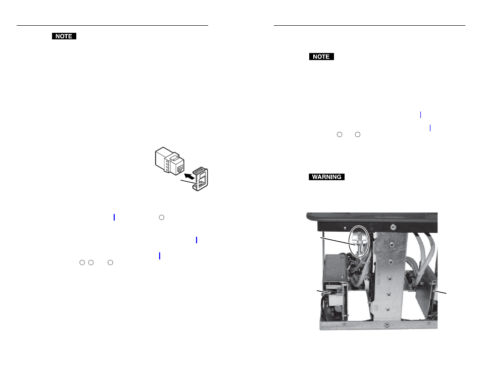
Locate the upper limit switch assembly (figure 3-7) inside
the enclosure.
Upper Limit
Switch
Assembly
Power
Supply
Control
Board
Figure 3-7 — Location of upper limit switch assembly
(seen from the side)
3-11
RJ-45 Bezel
Plug-in in AAP
Panel