5201 modem, Rs485 network, 3 rs485 network – YSI 5200 User Manual
Page 27
YSI Incorporated
25
5200 Recirculating System Monitor
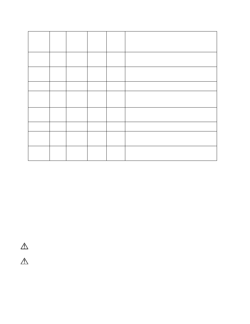
RJ-45 Pin
Number
RS232
Name
Direction RS232 TCP/IP
Signal
Function
1
DCD
I
NC
P
Signals module that remote device is
attached and powered on
2
RTS
O
NC
P
Flow control, to enable remote device to
send data
3 SG
P
P
Signal return (NOT chassis ground)
4
TXD
O
P
P
Serial data out, from YSI-5200 to remote
device
5
RXD
I
P
P
Serial data in, from remote device to YSI-
5200
6 SG
P
P
Signal return (NOT chassis ground)
7
CTS
I
NC
P
Flow control, to enable YSI-5200 to send
data on TXD
8
DTR
O
NC
P
Signals remote device that YSI-5200 is
attached and powered on
Table 3-1
To connect the 5200 to an EIA-232 device, it needs to be determined if the device connector wiring
follows the standard for data terminal equipment (DTE) or for data communication equipment (DCE). In
general, modems are wired as DCE devices and all other devices are wired as DTE; however, some
equipment manufacturers may deviate from the standard. In most cases, you use "straight through" RJ-45
cable. If you use "crossover" RJ-45 cable, the RJ-45 pins will be reversed.
3.7.2 5201
Modem
The YSI 5201 Modem is available only for use within the United States. For modem support outside the
US, an external modem registered for use within the local country is required. See Section 17
International Modem Support.
The YSI 5201 Modem mounts inside the 5200 case and connects to the RS232/TCP/IP Port. Refer to the
5201 Modem Installation Instructions, included with the modem, for details.
CAUTION: The phone line entering the 5200 case must be #26 AWG wire and must be sealed where it
enters the case or the instrument may be seriously damaged.
CAUTION: The ground wire from the 5201 Modem must be connected to the ground screw on the 5200
I/O plate.
3.7.3 RS485
Network
Connecting 5200s via the RS485 network is described in 8.1 RS485 Network.