Asus NCCH-DLE User Manual
Page 53
A S U S N C C H - D L E
A S U S N C C H - D L E
A S U S N C C H - D L E
A S U S N C C H - D L E
A S U S N C C H - D L E
2 - 3 3
2 - 3 3
2 - 3 3
2 - 3 3
2 - 3 3
1 4 .
1 4 .
1 4 .
1 4 .
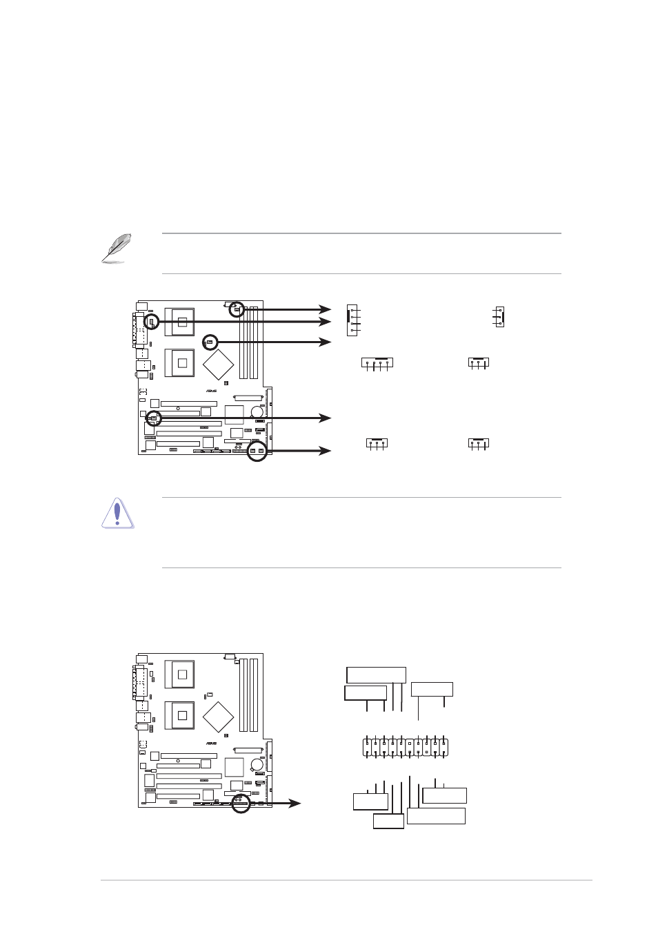
1 4 . CPU and system fan connectors (4-pin CPU_FAN1/2,
C P U a n d s y s t e m f a n c o n n e c t o r s ( 4 - p i n C P U _ F A N 1 / 2 ,
C P U a n d s y s t e m f a n c o n n e c t o r s ( 4 - p i n C P U _ F A N 1 / 2 ,
C P U a n d s y s t e m f a n c o n n e c t o r s ( 4 - p i n C P U _ F A N 1 / 2 ,
C P U a n d s y s t e m f a n c o n n e c t o r s ( 4 - p i n C P U _ F A N 1 / 2 ,
3 - p i n R E A R _ F A N 1 / 2 , 3 - p i n F R N T _ F A N 1 / 2 )
3 - p i n R E A R _ F A N 1 / 2 , 3 - p i n F R N T _ F A N 1 / 2 )
3 - p i n R E A R _ F A N 1 / 2 , 3 - p i n F R N T _ F A N 1 / 2 )
3 - p i n R E A R _ F A N 1 / 2 , 3 - p i n F R N T _ F A N 1 / 2 )
3 - p i n R E A R _ F A N 1 / 2 , 3 - p i n F R N T _ F A N 1 / 2 )
The fan connectors support cooling fans of 350mA~740mA (8.88W
max.) or a total of 2.1A~4.44A (53.28W max.) at +12V. Connect the
fan cables to the fan connectors on the motherboard, making sure
that the black wire of each cable matches the ground pin of the
connector.
Do not forget to connect the fan cables to the fan connectors. Lack of
sufficient air flow within the system may damage the motherboard
components. These are not jumpers! DO NOT place jumper caps on the
fan connectors!
The CPU fan connectors support either a 3-pin or a 4-pin fan cable plug.
Both connectors are slotted to ensure connection in correct orientation.
NCCH-DLE
®
GND
Rotation
+12V
CPU_FAN1
REAR_FAN1
GND
Rotation
+12V
FRNT_FAN2
GND
Rotation
+12V
CPU_FAN2
FRNT_FAN1
GND
Rotation
+12V
REAR_FAN2
GND
FAN Power
FAN Speed
PWM Control
GND
F
AN Power
F
AN Speed
PWM Control
NCCH-DLE Fan connectors
REAR_FAN1
CPU_FAN1
REAR_FAN2
CPU_FAN2
FRNT_FAN2
FRNT_FAN1
1 5 .
1 5 .
1 5 .
1 5 .
1 5 . System panel connector (20-pin PANEL1)
S y s t e m p a n e l c o n n e c t o r ( 2 0 - p i n P A N E L 1 )
S y s t e m p a n e l c o n n e c t o r ( 2 0 - p i n P A N E L 1 )
S y s t e m p a n e l c o n n e c t o r ( 2 0 - p i n P A N E L 1 )
S y s t e m p a n e l c o n n e c t o r ( 2 0 - p i n P A N E L 1 )
This connector accommodates several system front panel functions.
NCCH-DLE
®
NCCH-DLE System panel connector
PLED-
MLED
PWR
PLED+
+5V
Speaker
PLED
Ground
+5VSB
RESET
MLED
Ground
Reset
HD_LED+
HD_LED-
PWR_SW
LAN_LINK
LAN_ACT
Ground
SMI
ExtSMI#
Keylock
Ground
KEYLOCK
SPKR