Asus NCCH-DLE User Manual
Page 34
2 - 1 4
2 - 1 4
2 - 1 4
2 - 1 4
2 - 1 4
C h a p t e r 2 : H a r d w a r e i n f o r m a t i o n
C h a p t e r 2 : H a r d w a r e i n f o r m a t i o n
C h a p t e r 2 : H a r d w a r e i n f o r m a t i o n
C h a p t e r 2 : H a r d w a r e i n f o r m a t i o n
C h a p t e r 2 : H a r d w a r e i n f o r m a t i o n
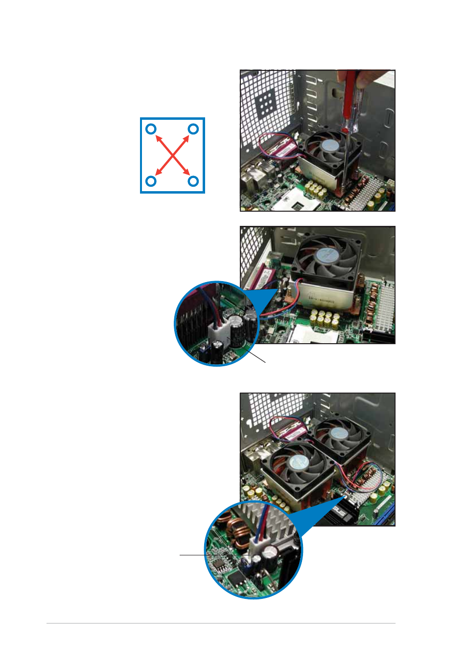
2.
Use a Phillips screwdriver to
tighten the four heatsink screws
in a diagonal sequence.
3.
Connect the fan cable to the 4-
pin connector labeled
CPU_FAN1.
4.
Repeat steps 1 to 3 to install
the other heatsink if you have
installed a second CPU, then
connect the fan cable to the 4-
pin connector labeled
CPU_FAN2.
The heatsinks appear as shown
when installed.
1
3
4
2
C P U 1 f a n c o n n e c t o r
C P U 1 f a n c o n n e c t o r
C P U 1 f a n c o n n e c t o r
C P U 1 f a n c o n n e c t o r
C P U 1 f a n c o n n e c t o r
(CPU_FAN1)
C P U 2 f a n c o n n e c t o r
C P U 2 f a n c o n n e c t o r
C P U 2 f a n c o n n e c t o r
C P U 2 f a n c o n n e c t o r
C P U 2 f a n c o n n e c t o r
( C P U _ F A N 2 )
( C P U _ F A N 2 )
( C P U _ F A N 2 )
( C P U _ F A N 2 )
( C P U _ F A N 2 )