Car2512te front-end, Preliminary data sheet, Input: 90v – GE Industrial Solutions CAR2512TE Front-End User Manual
Page 9: Output: 12 v, Standby @ 15w, Pmbus, Commands
GE
Preliminary Data Sheet
CAR2512TE Front-End
Input: 90V
AC
to 264V
AC
; Output: 12 V
DC
@ 2500W; 3.3/5V
DC
standby @ 15W
February 7, 2014
©2013 General Electric Company. All rights reserved.
Page 9
SMBAlert#
:
The µC driven SMBAlert# signal informs the
‘master/host’ controller that either a STATE or ALARM change
has occurred. Normally this signal is HI. The signal will change
to its LO level if the power supply has changed states and the
signal will be latched LO until the power supply receives a
‘clear’ instruction as outlined below. If the alarm state is still
present after the ‘clear_faults’ command has been received,
then the signal will revert back into its LO state again and will
latch until a subsequent ‘clear_faults’ signal is received from
the host controller.
The signal will be triggered for any state change, including the
following conditions;
VIN under or over voltage
Vout under or over voltage
IOUT over current
Over Temperature warning or fault
Fan Failure
Communication error
PEC error
Invalid command
Detected internal faults
The power supply will clear the SMBusAlert# signal (release the
signal to its HI state) upon the following events:
Receiving a CLEAR_FAULTS command
The main output recycled (turned OFF and then ON) via
the REMOTE ON/OFF signal pin
The main output recycled (turned OFF and then ON) by the
OPERATION command
Read back delay:
The power supply issues the SMBAlert #
notification as soon as the first state change occurred.
During
an event a number of different states can be transitioned to
before the final event occurs. If a read back is implemented
rapidly by the host a successive SMBAlert# could be triggered
by the transitioning state of the power supply. In order to avoid
successive SMBAlert# s and read back and also to avoid
reading a transitioning state, it is prudent to wait more than 2
seconds after the receipt of an SMBAlert# before executing a
read back. This delay will ensure that only the final state of the
power supply is captured.
Successive read backs:
Successive read backs to the power
supply should not be attempted at intervals faster than every
one second. This time interval is sufficient for the internal
processors to update their data base so that successive reads
provide fresh data.
Invalid commands or data:
The power supply notifies the
MASTER if a non-supported command has been sent or invalid
data has been received. Notification is implemented by setting
the appropriate STATUS and ALARM registers and setting the
SMBAlert# flag.
If a non-supported read is requested the power supply will
return all 0x00h.
PMBus
TM
Commands
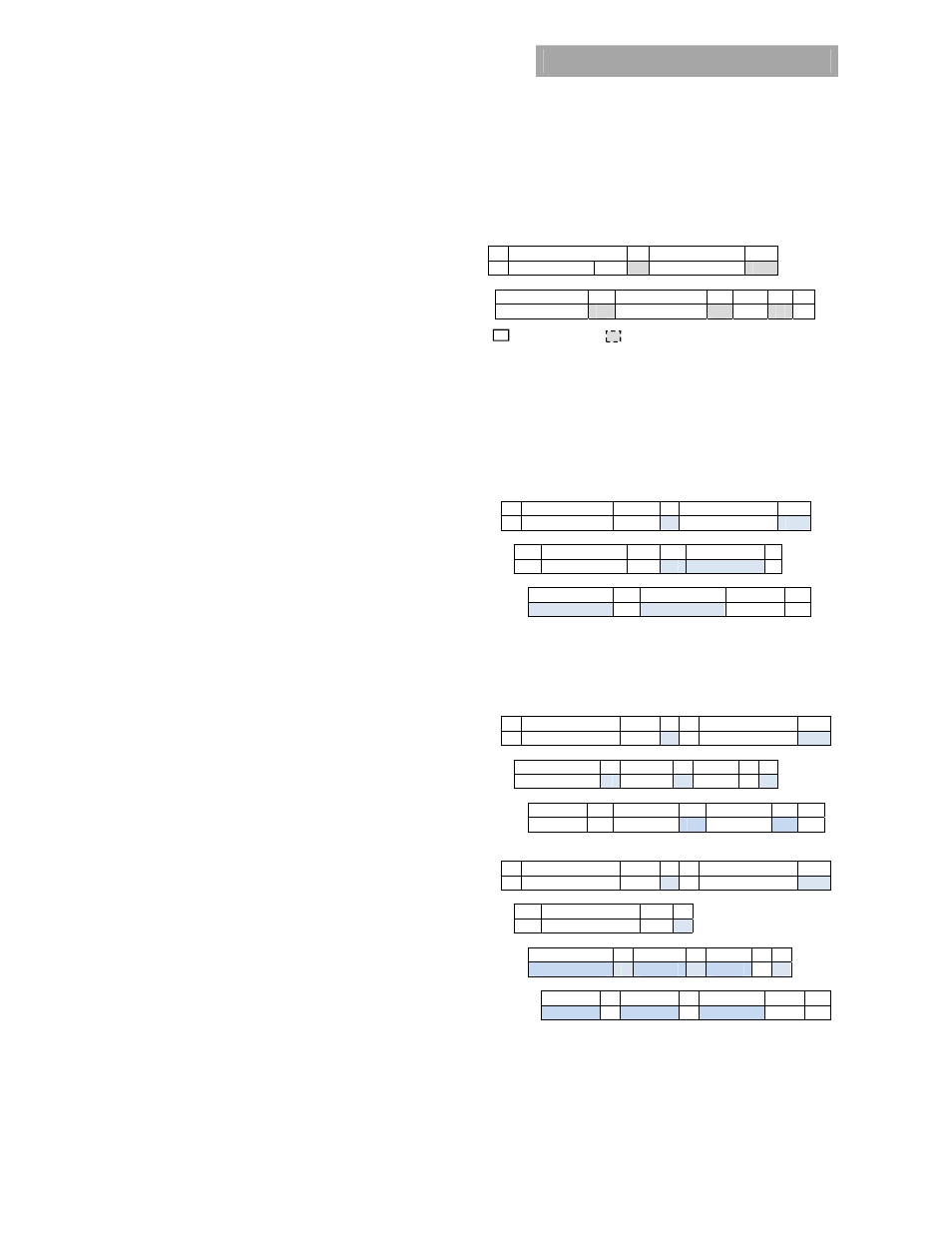
Standard instruction:
Up to two bytes of data may follow an
instruction depending on the required data content. Analog
data is always transmitted as LSB followed by MSB. PEC is
optional and includes the address and data fields.
1
8 1
8 1
S Slave address
Wr
A Command
Code A
8 1 8 1
8
1
1
Low data byte
A
High data byte
A PEC A P
Master to Slave Slave to Master
SMBUS annotations; S – Start , Wr – Write, Sr – re-Start, Rd –
Read,
A – Acknowledge, NA – not-acknowledged, P – Stop
Standard READ:
Up to two bytes of data may follow a READ
request depending on the required data content. Analog data
is always transmitted as LSB followed by MSB. PEC is
mandatory and includes the address and data fields
.
PEC is
optional and includes the address and data fields.
1
7 1
1
8 1
S
Slave address
Wr
A Command
Code A
1 7 1
1 8
1
Sr Slave
Address Rd A
LSB A
8 1 8
1
1
MSB A PEC No-ack
P
Block communications:
When writing or reading more than
two bytes of data at a time, BLOCK instructions for WRITE and
READ commands must be used instead of the Standard
Instructions
Block write format:
1
7 1
1
8 1
S
Slave address
Wr
A Command
Code A
8
1 8 1 8
1
Byte count = N
A Data
1 A Data
2 A
8 1 8 1 8 1
1
………. A Data
48 A PEC A P
Block read format:
1
7 1
1
8 1
S
Slave address
Wr
A Command
Code A
1 7 1
1
Sr Slave
Address Rd A
8 1
8
1
8
1
Byte count = N
A
Data 1
A Data 2
A
8 1 8 1 8 1 1
………. A
Data 48
A
PEC NoAck P