Car2512te front-end, Preliminary data sheet, Input: 90v – GE Industrial Solutions CAR2512TE Front-End User Manual
Page 7: Output: 12 v, Standby @ 15w, Control and status, Control signals
GE
Preliminary Data Sheet
CAR2512TE Front-End
Input: 90V
AC
to 264V
AC
; Output: 12 V
DC
@ 2500W; 3.3/5V
DC
standby @ 15W
February 7, 2014
©2012 General Electric Company. All rights reserved.
Page 7
Control and Status
Control hierarchy:
Some features, such as output voltage,
can be controlled both through hardware and firmware. For
example, the output voltage is controlled both by the signal pin
(Vprog) and the PMBus command, (Vout_command) .
Using output voltage as an example; the Vprog signal pin has
ultimate control of the output voltage until the Vprog is either >
3V
DC
or a no connect. When the programming signal via Vprog
is either a no connect or > 3V
DC
, it is ignored, the output
voltage is set at its nominal 12V
DC
and the unit output voltage
can be controlled via the PMBus command, (Vout_command).
Analog controls:
Details of analog controls are provided in
this data sheet under Signal Definitions.
Common ground:
All signals and outputs are referenced to
Output return. These include ‘V
STDBY
return’ and ‘Signal return’.
reset the soft start circuitry of the individual power supplies.
Auto_restart:
Auto-restart is the default configuration for
recovering from over-current and over-temperature
shutdowns.
An overvoltage shutdown is followed by three attempted
restarts, each restart delayed 1 second, within a 1 minute
window. If within the 1 minute window three attempted
restarts failed, the unit will latch OFF. If less than 3 shutdowns
occur within the 1 minute window then the count for latch OFF
resets and the 1 minute window starts all over again.
Restart after a lachoff:
To restart after a latch_off either of
four restart mechanisms are available. The hardware pin
Remote ON/OFF may be turned OFF and then ON. The unit
may be commanded to restart via i2c through the Operation
command by first turning OFF then turning ON . The third way
to restart is to remove and reinsert the unit. The fourth way is
to turn OFF and then turn ON ac power to the unit. The fifth
way is by changing firmware from latch off to restart. Each of
these commands must keep the power supply in the OFF state
for at least 2 seconds, with the exception of changing to
restart.
A successful restart shall clear all alarm registers.
A power system that is comprised of a number of power
supplies could have difficulty restarting after a shutdown event
because of the non-synchronized behavior of the individual
power supplies. Implementing the latch-off mechanism
permits a synchronized restart that guarantees the
simultaneous restart of the entire system.
A synchronous restart can be implemented by;
1. Issuing a GLOBAL OFF and then ON command to all power
supplies,
2. Toggling Off and then ON the Remote ON/OFF signal
3. Removing and reapplying input commercial power to the
entire system.
It is good practice to turn OFF the power supplies for about 20
– 30 seconds in order to discharge all internal bias supplies
and reset the soft start circuitry of the individual power
supplies.
Control Signals
All signals are referenced to ‘Signal Return’.
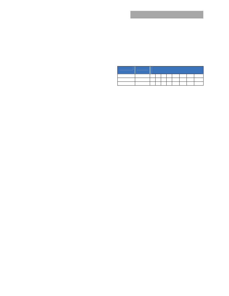
Device addressing:
The microcontroller (MCU) and the EEPROM
have the following addresses:
Device
Address
Address Bit Assignments
(Most to Least Significant)
MCU
0xBx 1 0 1 1 A2 A1 A0 R/W
Broadcast 0x00 0 0 0 0 0 0 0 0
EEPROM
0xAx 1 0 1 0 A2 A1 A0 R/W
Address lines (A2, A1, A0):
These signal pins allow up to eight
(8) modules to be addressed on a single I²C bus. The pins are
pulled HI internally. For logic LO connect to ‘Output Return’.
Global broadcast:
This is a powerful command because it
instruct all power supplies to respond simultaneously. A read
instruction should never be accessed globally. The power
supply should issue an ‘invalid command’ state if a ‘read’ is
attempted globally.
For example, changing the ‘system’ output voltage requires the
global broadcast so that all paralleled power supplies change
their output simultaneously. This command can also turn OFF
the ‘main’ output or turn ON the ‘main’ output of all power
supplies simultaneously. Unfortunately, this command does
have a side effect. Only a single power supply needs to pull
down the ninth acknowledge bit. To be certain that each power
supply responded to the global instruction, a READ instruction
should be executed to each power supply to verify that the
command properly executed. The GLOBAL BROADCAST
command should only be executed for write instructions to
slave devices.
Voltage programming (Vprog):
An analog voltage on this
signal can vary the output voltage ± 10% of nominal, from
10.8V
DC
to 13.2V
DC
. The equation of this signal is:
V
OUT
= 10.8 (Vprog * 0.96) where Vprog = 0 to 2.5V
DC
Between 2.5 and 3V the output stays at 13.2V
DC
. If Vprog is >
3V, or left open, the programming signal is ignored and the
unit output is set at the setpoint of 12V
DC
.
Load share (Ishare):
This is a single wire analog signal that is
generated and acted upon automatically by power supplies
connected in parallel. The Ishare pins should be tied together
for power supplies if active current share among the power
supplies is desired. No resistors or capacitors should get
connected to this pin.
Remote_ON/OFF:
Controls presence of the 12V
DC
output
voltage. A logic LO on this signal pin turns OFF the 12V
DC
output.
Interlock:
This is a short signal pin that controls the presence
of the 12V
DC
main output. This pin should be connected to
‘output return’ on the system side of the output connector. The
purpose of this pin is to ensure that the output turns ON after
engagement of the power blades and turns OFF prior to
disengagement of the power blades.