36v prolynx, 5a: non-isolated dc-dc power modules, Data sheet – GE Industrial Solutions 9-36V ProLynx 5A User Manual
Page 30
GE
Data Sheet
9-36V ProLynx
TM
5A: Non-Isolated DC-DC Power Modules
9Vdc –36Vdc input; 3Vdc to 18Vdc output; 5A to 2.5A Scaled output current
9Vdc –24Vdc input; -3.3Vdc to -18Vdc output; 5A to 0.7A Scaled output current
July 23, 2013
©2012 General Electric Company. All rights reserved.
Page 30
Output Ripple
Output ripple curves for input voltages of 9Vin, 12Vin and 24Vin
Ripple at intermediate input voltages can be estimated
through extrapolation. Output Voltage is also roughly
proportional to load current level.
Table 7. Peak to Peak Ripple in mV with a 10uF external
capacitor at different load levels
-3.3Vout
0.1A 50%Load
100%Load
9Vin 23 103
(1.75A)
174
12Vin 26 109
(1.9A)
177
24Vin 36 134
(2.5A)
214
-5Vout
0.1A
50%Load
100%Load
9Vin 27 114
(1.35A)
196
12Vin 31 115
(1.55A)
195
24Vin 40 127
(2.2A)
217
-12Vout
0.1A
50%Load
100%Load
9Vin 35 108
(0.65A)
195
12Vin 44 107
(0.8A)
206
24Vin 74 114
(1.25A)
217
-18Vout
0.1A
50%Load
100%Load
9Vin 43 77
(0.35A)
165
12Vin 53 80
(0.45A)
165
18Vin 76 122
(0.55A)
210
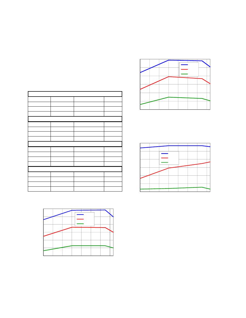
9Vin
Out
pu
t Rip
pl
e Vol
tag
e
(m
Vp-p)
Output Voltage (Vdc)
Figure 66. Output ripple with 1x10µF, 2x10µF or 4x10µF
output ceramic capacitors (max load).
12Vin
O
utput Rip
ple V
oltag
e
(mV
p-p)
Output Voltage (Vdc)
Figure 67. Output ripple with 1x10µF, 2x10µF or 4x10µF
output ceramic capacitors (max load).
18Vin(-12Vo to -18Vo) / 24Vin(-3.3Vo to -12Vo)
Outpu
t Rip
pl
e Volt
age
(mVp-p)
Output Voltage (Vdc)
Figure 68. Output ripple with 1x10µF, 2x10µF or 4x10µF
output ceramic capacitors (max load).
50
75
100
125
150
175
200
-18
-16
-14
-12
-10
-8
-6
-4
1x10uF
2x10uF
4x10uF
50
75
100
125
150
175
200
-18
-16
-14
-12
-10
-8
-6
-4
1x10uF
2x10uF
4x10uF
75
100
125
150
175
200
225
-18
-16
-14
-12
-10
-8
-6
-4
1x10uF
2x10uF
4x10uF