36v prolynx, 5a: non-isolated dc-dc power modules, Data sheet – GE Industrial Solutions 9-36V ProLynx 5A User Manual
Page 15
GE
Data Sheet
9-36V ProLynx
TM
5A: Non-Isolated DC-DC Power Modules
9Vdc –36Vdc input; 3Vdc to 18Vdc output; 5A to 2.5A Scaled output current
9Vdc –24Vdc input; -3.3Vdc to -18Vdc output; 5A to 0.7A Scaled output current
July 23, 2013
©2012 General Electric Company. All rights reserved.
Page 15
Thermal Considerations
Power modules operate in a variety of thermal environments;
however, sufficient cooling should always be provided to help
ensure reliable operation.
Considerations include ambient temperature, airflow, module
power dissipation, and the need for increased reliability. A
reduction in the operating temperature of the module will
result in an increase in reliability. The thermal data presented
here is based on physical measurements taken in a wind
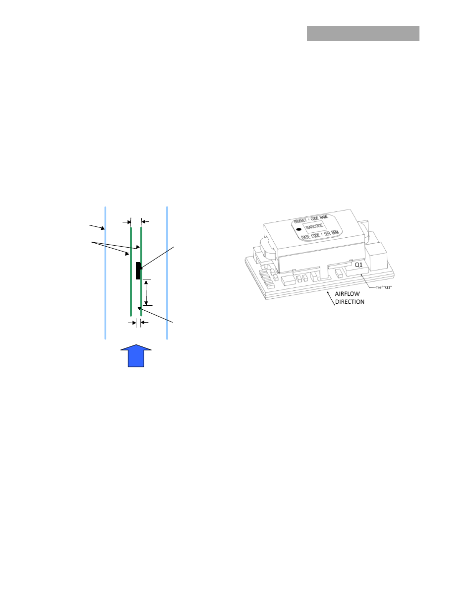
tunnel. The test set-up is shown in Figure 39. The preferred
airflow direction for the module is in Figure 40. The derating
data applies to airflow in either direction of the module’s short
axis.
Air
flow
x
Power Module
Wind Tunnel
PWBs
12.7_
(0.50)
76.2_
(3.0)
Probe Location
for measuring
airflow and
ambient
temperature
25.4_
(1.0)
Figure 39. Thermal Test Setup.
The thermal reference points, T
ref
used in the specifications are
also shown in Figure 40. For reliable operation the
temperatures at these points should not exceed 115
o
C. The
output power of the module should not exceed the rated
power of the module (Vo,set x Io,max).
Please refer to the Application Note “Thermal Characterization
Process For Open-Frame Board-Mounted Power Modules” for a
detailed discussion of thermal aspects including maximum
device temperatures.
Figure 40. Preferred airflow direction and location of hot-
spot of the module (Tref).