36v prolynx, 5a: non-isolated dc-dc power modules, Data sheet – GE Industrial Solutions 9-36V ProLynx 5A User Manual
Page 11: Safety considerations
GE
Data Sheet
9-36V ProLynx
TM
5A: Non-Isolated DC-DC Power Modules
9Vdc –36Vdc input; 3Vdc to 18Vdc output; 5A to 2.5A Scaled output current
9Vdc –24Vdc input; -3.3Vdc to -18Vdc output; 5A to 0.7A Scaled output current
July 23, 2013
©2012 General Electric Company. All rights reserved.
Page 11
Output Filtering
The 9-36V ProLynx
TM
modules are designed for low output
ripple voltage and will meet the maximum output ripple
specification with 0.1 µF ceramic and 10 µF ceramic
capacitors at the output of the module. However, additional
output filtering may be required by the system designer for a
number of reasons. First, there may be a need to further
reduce the output ripple and noise of the module. Second, the
dynamic response characteristics may need to be customized
to a particular load step change.
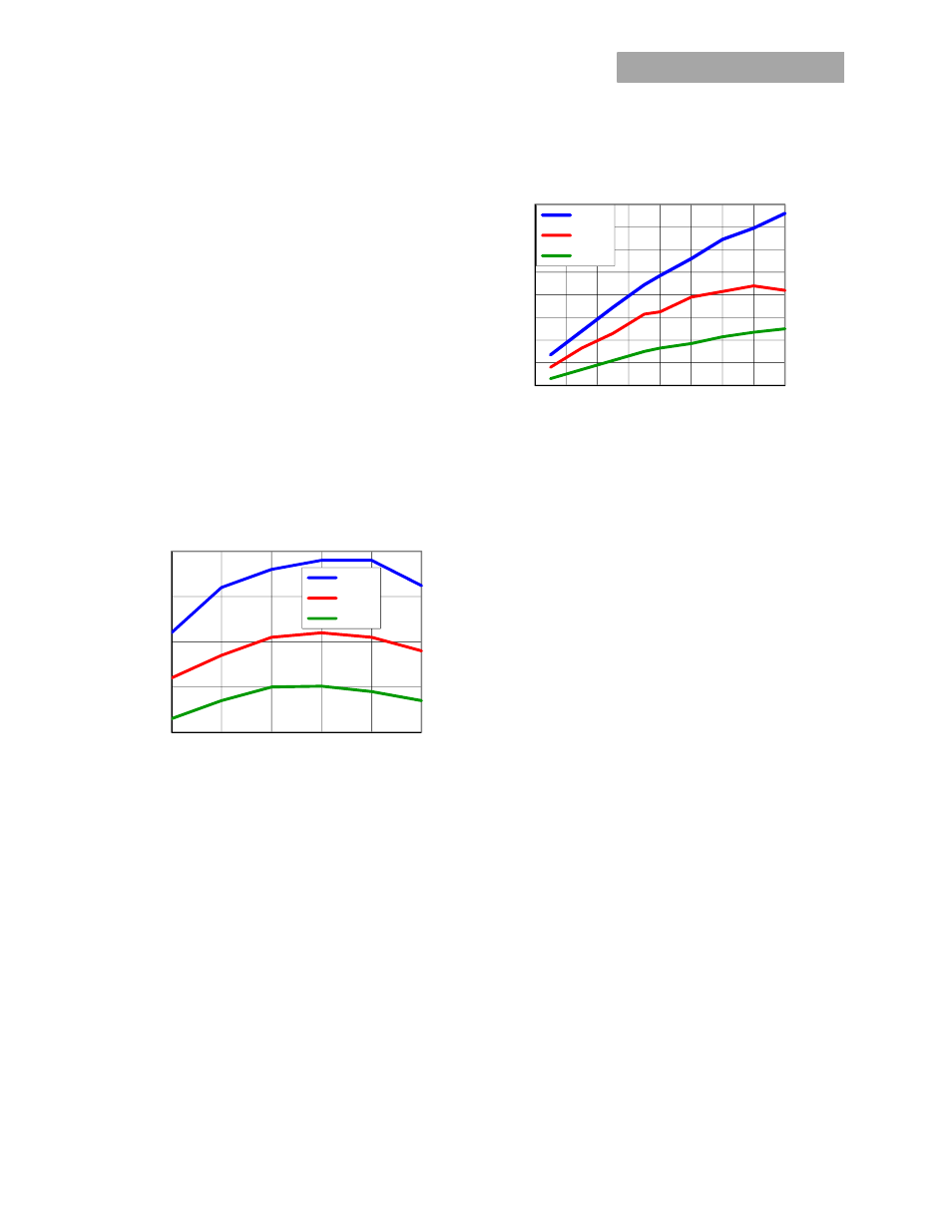
To reduce the output ripple and improve the dynamic
response to a step load change, additional capacitance at the
output can be used. Low ESR polymer and ceramic capacitors
are recommended to improve the dynamic response of the
module. Figures 30 and 31 provide output ripple information
for different external capacitance values at various Vo and for
full load currents. For stable operation of the module, limit the
capacitance to less than the maximum output capacitance as
specified in the electrical specification table. Optimal
performance of the module can be achieved by using the
Tunable Loop
TM
feature described later in this data sheet.
Figure 30. Output ripple voltage for various output voltages
with external 1x10 µF, 2x10 µF or 4x10 µF ceramic
capacitors at the output (max. load). Input voltage is 12V.
Figure 31. Output ripple voltage for various output voltages
with external 1x10 µF, 2x10 µF or 4x10 µF ceramic capacitors
at the output (max. load). Input voltage is 28V.
Safety Considerations
For safety agency approval the power module must be
installed in compliance with the spacing and separation
requirements of the end-use safety agency standards, i.e., UL
60950-1 2nd, CSA C22.2 No. 60950-1-07, DIN EN 60950-1:2006
+ A11 (VDE0805 Teil 1 + A11):2009-11; EN 60950-1:2006 +
A11:2009-03.
For the converter output to be considered meeting the
requirements of safety extra-low voltage (SELV), the input must
meet SELV requirements. The power module has extra-low
voltage (ELV) outputs when all inputs are ELV.
The input to these units is to be provided with a fast-acting
fuse with a maximum rating of 8A in the positive input lead
.
10
20
30
40
50
3
4
5
6
7
8
Ri
ppl
e
(mV
p-p
)
Output Voltage(Volts)
1x10uF
2x10uF
4x10uF
10
30
50
70
90
110
130
150
170
2
4
6
8
10
12
14
16
18
Ri
pp
le
(m
V
p
-p
)
Output Voltage(Volts)
1x10uF
2x10uF
4x10uF