36v prolynx, 5a: non-isolated dc-dc power modules, Data sheet – GE Industrial Solutions 9-36V ProLynx 5A User Manual
Page 24: Negative output operation
GE
Data Sheet
9-36V ProLynx
TM
5A: Non-Isolated DC-DC Power Modules
9Vdc –36Vdc input; 3Vdc to 18Vdc output; 5A to 2.5A Scaled output current
9Vdc –24Vdc input; -3.3Vdc to -18Vdc output; 5A to 0.7A Scaled output current
July 23, 2013
©2012 General Electric Company. All rights reserved.
Page 24
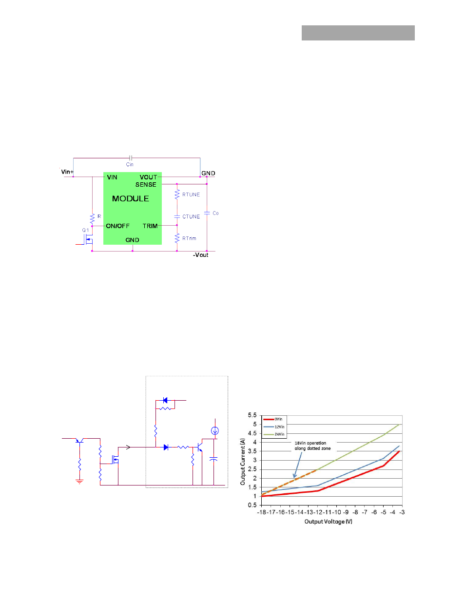
Negative Output Operation
Basic Scheme
The 9-36V ProLynx
TM
modules can also be used to create
negative output voltages from a positive input voltage.
Changing the input connection to as shown in Figure 44
converts the module from a synchronous buck converter to a
synchronous flyback converter
Figure 44. Schematic Connection of 5A ProLynx module for
negative output applications.
Remote Enable
Figures 33 and 34 still apply for remote On/Off operation.
However the On/Off threshold is now with respect to –Vout
instead of Ground. Before the module turns on, output is zero
so GND and –Vout are at the same potential. After the
module turns on, -Vout moves down and so will the ON/OFF
threshold. The following level shifting circuit can be used in
applications to limit exposure of the negative output voltage
to the On/Off circuitry.
Figure 45. On/Off Level Shifting Circuit for the 5A ProLynx
module for negative output applications.
Instead of directly turning Q1 On, the level shifting circuit is
used to turn Q1 On by first turning Q2 ON. When Q1 is in the
ON state, the ON/OFF pin is pulled low causing transistor Q5
to be OFF and the module to be turned ON. Both Q1 and Q2
are external transistors. To turn the module OFF, Q2 is turned
OFF, which turns Q1 OFF causing the ON/OFF pin to be pulled
high turning Q5 ON and the module to be turned OFF. If the
On/Off pin is left floating, the module will be in the OFF state.
Input Voltage Range
The 9-36V ProLynx
TM
modules when connected in a negative
output application will support a maximum input voltage
which is also a function of the output voltage. The sum of the
applied input voltage and magnitude of the output voltage
cannot exceed 36V. Vin(applied) +|Vout| ≤ 36 and Vout≤-3V. For
e.g. with a -12V output system the max input voltage that can
applied is only 24V. However, Figure 35 showing variation of
output voltage with Input Voltage should still be considered for
determining the required minimum input voltage.
Input voltage turn-on threshold remains the same as the
positive output connection. However the input turn-off
threshold tracks the output voltage and is reduced by the
same level. The listed input Turn-Off threshold of 7.35V when
applied to a -3.3Vout application will be measured as a 4.05V
(7.35V – 3.3V) threshold. Operating at input voltages below 9V
may cause the module to shut down earlier due to OCP
inception
Output Voltage Range
The 9-36V ProLynx
TM
modules will support the values of trim
resistors indicated in Table 1 to generate the same output
voltage, except with sign inversion. For an output voltage of
12V or higher the maximum input voltage will have to be
proportionally reduced from 24Vin so that the sum of the
magnitudes does not exceed 36V
Overcurrent Protection
The 9-36V ProLynx modules will
automatically scale current
limit with output voltage through an inverse relationship of the
current limit threshold even in negative output voltage mode.
This feature is shown graphically in Fig. 46, allows higher
output currents to be drawn from the module at lower output
voltages thereby optimizing the power delivery capability of
the module.
Figure 46. Graph showing maximum output current
capability at different output voltages.
ISS1
I
ON/OFF
CSS1
Q1
ON/OFF
GND
+
V
22K
Q5
22K
D3
MODULE
PWM Enable
ON/OFF
22K
D4
22K
+5V
R2
R1
Q2
-
10K
ENABLE