36v prolynx, 5a: non-isolated dc-dc power modules, Data sheet – GE Industrial Solutions 9-36V ProLynx 5A User Manual
Page 13: Ω − = k vo rtrim 7 . 0 70
GE
Data Sheet
9-36V ProLynx
TM
5A: Non-Isolated DC-DC Power Modules
9Vdc –36Vdc input; 3Vdc to 18Vdc output; 5A to 2.5A Scaled output current
9Vdc –24Vdc input; -3.3Vdc to -18Vdc output; 5A to 0.7A Scaled output current
July 23, 2013
©2012 General Electric Company. All rights reserved.
Page 13
Once the unit goes into thermal shutdown it will then wait to
cool before attempting to restart.
Input Undervoltage Lockout
At input voltages below the input undervoltage lockout limit,
the module operation is disabled. The module will begin to
operate at an input voltage above the undervoltage lockout
turn-on threshold.
Output Voltage Programming
The output voltage of the 9-36V ProLynx
TM
module can be
programmed to any voltage from 3Vdc to 18Vdc by
connecting a resistor between the Trim and GND pins of the
module. Certain restrictions apply on the output voltage set
point depending on the input voltage. These are shown in the
Output Voltage vs. Input Voltage Set Point Area plot in Fig. 35.
Without an external resistor between Trim and GND pins, the
output of the module will be 0.7Vdc. To calculate the value of
the trim resistor, Rtrim for a desired output voltage, use the
following equation:
(
)
Ω
−
=
k
Vo
Rtrim
7
.
0
70
Rtrim is the external resistor in kΩ, and Vo is the desired
output voltage.
Figure 35. Output Voltage vs. Input Voltage Set Point Area
plot showing limits where the output voltage can be set for
different input voltages.
Table 1 provides Rtrim values required for some common
output voltages.
Table 1
V
O, set
(V)
Rtrim (KΩ)
3.3 26.92
5 16.27
6 13.20
9 8.43
12 6.19
15 4.89
18 4.04
By using a ±0.5% tolerance trim resistor with a TC of ±100ppm,
a set point tolerance of ±1.5% can be achieved as specified in
the electrical specification.
Remote Sense
The 9-36V ProLynx
TM
power modules have a Remote Sense
feature to minimize the effects of distribution losses by
regulating the voltage between the VS+ and Vo pin. The
voltage between the VS+ pin and Vo pin should not exceed
0.5V.
V
O
(+)
TRIM
GND
R
trim
LOAD
V
IN
(+)
ON/OFF
VS+
Figure 36. Circuit configuration for programming output
voltage using an external resistor.
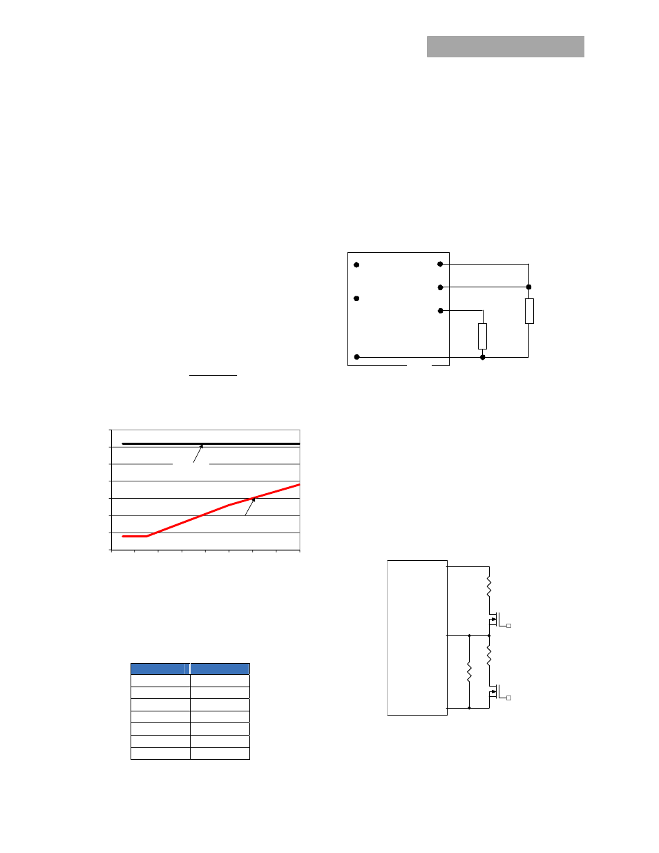
Voltage Margining
Output voltage margining can be implemented in the 9-36V
ProLynx
TM
modules by connecting a resistor, R
margin-up
, from the
Trim pin to the ground pin for margining-up the output voltage
and by connecting a resistor, R
margin-down
, from the Trim pin to
output pin for margining-down. Figure 37 shows the circuit
configuration for output voltage margining. The POL
Programming Tool, available at
www.lineagepower.com
under
the Design Tools section, also calculates the values of R
margin-up
and R
margin-down
for a specific output voltage and % margin
Please consult your local GE technical representative for
additional details.
Figure 37. Circuit Configuration for margining Output
voltage
5
10
15
20
25
30
35
40
2
4
6
8
10
12
14
16
18
Input
V
o
lt
a
g
e
(v
)
Output Voltage (V)
Lower Limit
Upper Limit
Vo
MODULE
GND
Trim
Q1
Rtrim
Rmargin-up
Q2
Rmargin-down