36v prolynx, 5a: non-isolated dc-dc power modules, Data sheet – GE Industrial Solutions 9-36V ProLynx 5A User Manual
Page 3: Electrical specifications
GE
Data Sheet
9-36V ProLynx
TM
5A: Non-Isolated DC-DC Power Modules
9Vdc –36Vdc input; 3Vdc to 18Vdc output; 5A to 2.5A Scaled output current
9Vdc –24Vdc input; -3.3Vdc to -18Vdc output; 5A to 0.7A Scaled output current
July 23, 2013
©2012 General Electric Company. All rights reserved.
Page 3
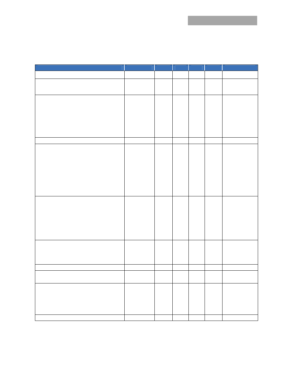
Electrical Specifications
(continued)
Parameter
Device
Symbol
Min
Typ
Max
Unit
Output Voltage Set-point
All
V
O, set
-2.0 +2.0
%
V
O, set
Output Voltage
All
V
O, set
-2.5
⎯
+2.5 %
V
O, set
(Over all operating input voltage, resistive load, and
temperature conditions until end of life)
Adjustment Range (elected by an external resistor)
(Some output voltages may not be possible depending
on the input voltage – see Feature Descriptions Section)
All V
O
3 18
Vdc
Output Regulation
Line (V
IN
=V
IN, min
to V
IN, max
) All
⎯
0.4 %
V
O, set
Load (I
O
=I
O, min
to I
O, max
) All
⎯
0.4 %
V
O, set
Temperature (T
ref
=T
A, min
to T
A, max
) All
⎯
0.4 %
V
O, set
Remote Sense Range
All
0.5
Vdc
Output Ripple and Noise on nominal output
(V
IN
=V
IN, nom
and I
O
=I
O, min
to I
O, max
Co = 0.1μF // 10 μF
ceramic capacitors)
Vout=3.3V, Vin=28V
Peak-to-Peak (5Hz to 20MHz bandwidth)
All
45
mV
pk-pk
RMS (5Hz to 20MHz bandwidth)
All
14
mV
rms
Vout=18V, Vin=28V
Peak-to-Peak (5Hz to 20MHz bandwidth)
All
143
mV
pk-pk
RMS (5Hz to 20MHz bandwidth)
All
47
mV
rms
External Capacitance
1
Without the Tunable Loop
TM
ESR ≥ 1 mΩ
All
C
O, max
0
⎯
47
μF
ESR ≥ 10 mΩ
All
C
O, max
0
⎯
100
μF
With the Tunable Loop
TM
ESR ≥ 0.15 mΩ All
C
O, max
0
⎯
100
μF
ESR ≥ 10 mΩ All
C
O, max
0
⎯
2000*
μF
Output Current (Vo=3V)
All
I
o
0 5
Adc
Vo=5V
All
I
o
0 4.7
Adc
Vo=12V
All
I
o
0 3.5
Adc
Vo=18V
All
I
o
0 2.5
Adc
Output Current Limit Inception (Hiccup Mode )
All
I
O, lim
160
%
I
o,max
Output Short-Circuit Current 12Vin 25C
All
I
O, s/c
2
Adc
(V
O
≤250mV) ( Hiccup Mode ) 28Vin
Efficiency (I
O
=I
O, max ,
V
O
= V
O,set
)
V
IN
= 12Vdc, T
A
=25°C V
O, set
= 3.3Vdc
η
91.0
%
V
IN
= 12Vdc, T
A
=25°C V
O, set
= 5Vdc
η
93.3
%
V
IN
= 28Vdc, T
A
=25°C V
O,set
= 12Vdc
η
94.7
%
V
IN
= 28Vdc, T
A
=25°C V
O,set
= 18Vdc
η
95.9
%
Switching Frequency
All
f
sw
⎯
300
⎯
kHz
1
Depending on Input and Output Voltage, external capacitors require using the new Tunable Loop
TM
feature to ensure that the module is
stable as well as getting the best transient response. See the Tunable Loop
TM
section for details.
* Larger values may be possible at specific output voltages. Please consult your GE Technical representative for additional details.