36v prolynx, 5a: non-isolated dc-dc power modules, Data sheet – GE Industrial Solutions 9-36V ProLynx 5A User Manual
Page 14: Module
GE
Data Sheet
9-36V ProLynx
TM
5A: Non-Isolated DC-DC Power Modules
9Vdc –36Vdc input; 3Vdc to 18Vdc output; 5A to 2.5A Scaled output current
9Vdc –24Vdc input; -3.3Vdc to -18Vdc output; 5A to 0.7A Scaled output current
July 23, 2013
©2012 General Electric Company. All rights reserved.
Page 14
Tunable Loop
TM
The 9-36V ProLynx
TM
modules have a new feature that
optimizes transient response of the module called Tunable
Loop
TM
.
External capacitors are usually added to the output of the
module for two reasons: to reduce output ripple and noise (see
Figs 30 and 31) and to reduce output voltage deviations from
the steady-state value in the presence of dynamic load current
changes. Adding external capacitance however affects the
voltage control loop of the module, typically causing the loop
to slow down with sluggish response. Larger values of external
capacitance could also cause the module to become unstable.
The Tunable Loop
TM
allows the user to externally adjust the
voltage control loop to match the filter network connected to
the output of the module. The Tunable Loop
TM
is implemented
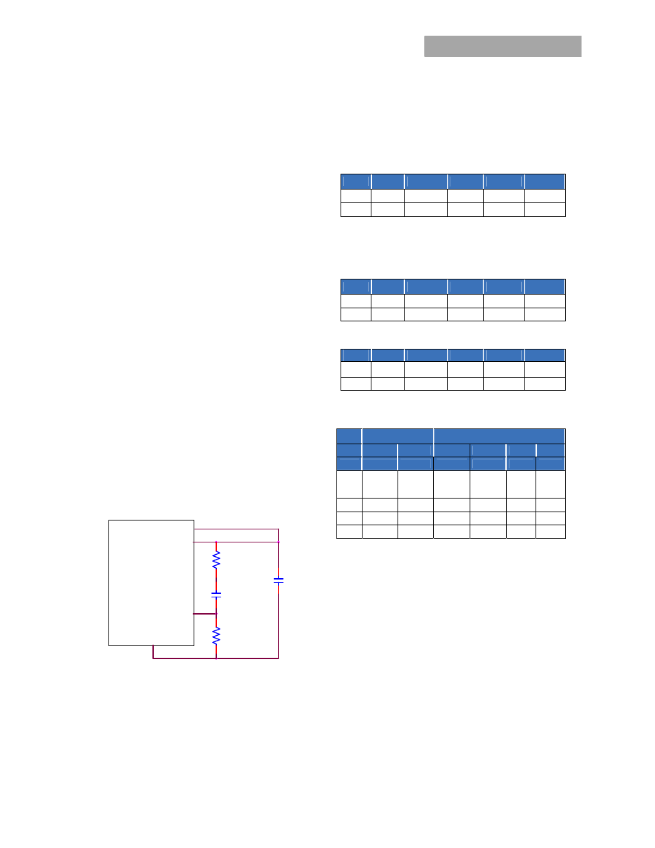
by connecting a series R-C between the SENSE and TRIM pins
of the module, as shown in Fig. 38. This R-C allows the user to
externally adjust the voltage loop feedback compensation of
the module.
Recommended values of R
TUNE
and C
TUNE
for different output
capacitor combinations are given in Tables 2, 3 and 4. Tables 2
and 3 show recommended values of R
TUNE
and C
TUNE
for
different values of ceramic output capacitors up to 100
μ
F that
might be needed for an application to meet output ripple and
noise requirements. Selecting R
TUNE
and C
TUNE
according to
Tables 2 and 3 will ensure stable operation of the module
In applications with tight output voltage limits in the presence
of dynamic current loading, additional output capacitance will
be required. Table 4 lists recommended values of R
TUNE
and
C
TUNE
in order to meet 2% output voltage deviation limits for
some common output voltages in the presence of a 50% of full
load step change with an input voltage of 12 or 28V.
Figure. 38. Circuit diagram showing connection of R
TUME
and
C
TUNE
to tune the control loop of the module
.
Please contact your GE technical representative to obtain more
details of this feature as well as for guidelines on how to select
the right value of external R-C to tune the module for best
transient performance and stable operation for other output
capacitance values or input voltages other than 12 / 28V.
Table 2. General recommended values of of R
TUNE
and C
TUNE
for Vin=12V and various external ceramic capacitor
combinations.
Vo=5V
Co
1x10
μF
1x22
μF
2x22
μF
4x22
μF
6x22
μF
R
TUNE
330 270 270 220 180
C
TUNE
680pF 1200pF 2700pF 4700pF 5600pF
Table 3. General recommended values of of R
TUNE
and C
TUNE
for Vin=28V and various external ceramic capacitor
combinations.
Vo=5V
Co
1x10
μF
1x22
μF
2x22
μF
4x22
μF
6x22
μF
R
TUNE
330 220 220 150 150
C
TUNE
220pF 390pF 680pF 1000pF 1800pF
Vo=12V
Co
1x10
μF
1x22
μF
2x22
μF
4x22
μF
6x22
μF
R
TUNE
330 330 270 270 180
C
TUNE
120pF 470pF 1000pF 1800pF 2700pF
Table 4. Recommended values of R
TUNE
and C
TUNE
to obtain
transient deviation of 2% of Vout for a 50% of full load step.
Vin
12V
28V
Vo
3.3V
5V
3.3V
5V
12V
18V
∆I
2.5A
2.35A
2.5A
2.35A
1.75A
1.5A
Co 1x330μF
OsCon
1x330
μF
OsCon
1x330
μF
OsCon
1x330
μF
OsCon 2x22μF 1x22μF
R
TUNE
180 180 180 220 270
330
C
TUNE
22nF 22nF 6800pF
6.8nF
470pF
47pF
ΔV
39mV 37mV 36mV 34mV
220mV 310mV
MODULE
VOUT
SENSE
TRIM
GND
RTUNE
CTUNE
RTrim
C O