GE Industrial Solutions Entelliguard TU, MicroVersaTrip Plus and PM Conversion Kits User Manual
Page 8
8
Installing and Adjusting the Flux Shifter
Assembly
Use the following procedures to install and adjust the
new flux shifter assembly, shown in Figure 4.
Numbers in brackets in the text refer to the numbered
parts in Figure 4. The breaker should still be resting
on its back from the previous procedure (removing
the old components).
Installing the Flux Shifter Assembly
Figures 6 and 7 show views of the completed flux
shifter installation.
1. Locate the flux shifter mounting hole, shown in
Figure 5.
2. For LA Gold breaker install the new flux shifter
assembly as shown in fig 7. For La gold units,
the # 6 screw protruding from the back of the
flux shifter assembly will plug in to the
mounting hole A (Figure 5).and position lower
mounting hole of the assembly over mounting
hole B (Figure 5).
By using mounting spacer, Hex bolt and lock
washer (provided in hardware kit) secure flux
shifter assembly to breaker mechanism side
plate as shown in fig 7.
Note:
Before installing flux shifter assembly, loosen reset-
bushing screw as shown in figure7, so that reset
bushing’s position can be adjusted between breaker
reset link and breaker trip latch while unit is being
positioned for mounting.
3. For RL breakers install the flux shifter assembly
as shown in figure 6 for RL units. The #6 screw
protruding from the back of the flux shifter
assembly will plug in to mounting hole A (Figure
5). Before mounting flux shifter assembly ,
remove the mounting hardware (hex screw,
washer, lock washer) secured to RL mounting
plate and reinstall as shown in fig 6 after unit is
properly positioned over drilled out mounting
hole C.
Once unit is completely adjusted (Instructions to
adjust are in later section of this manual) ,
breaker reset spring is to be anchored as shown
in fig 6.
Note:
Before installing flux shifter assembly, loosen reset-
bushing screw as shown in figure 7, so that reset
bushing’s position can be adjusted between breaker
reset link and breaker latch while unit is being
positioned for mounting.
Flux Shifter Adjustment
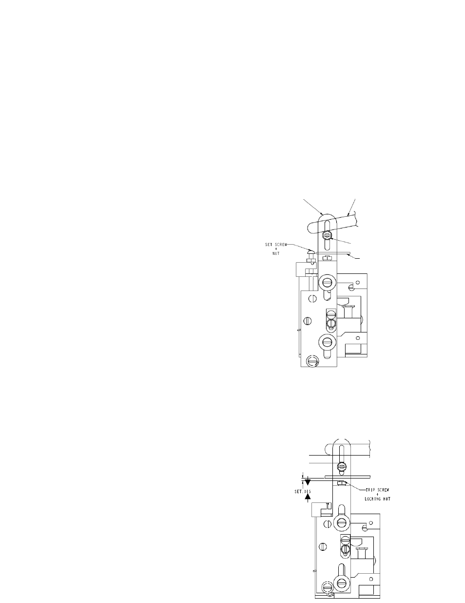
1. Figure 4 (a)
With the breaker in the tripped and open position,
move reset bushing in to engagement with the
breaker-reset lever. Lock in this position (for RL
breakers, hold link down while moving up bushing
or else link will move). Remove set screw and nut
and dispose.
2. Figure 4 (b)
With breaker closed adjust trip screw on trip slide
to 0.015 gap as shown. Lock in position with
locking nut in this closed position check that
dimension (A) is greater than 0.170. Dimension A
is meant to be an initial check to insure that the
device is properly installed. It may vary slightly
from
breaker to
breaker.
Reset
Breaker
reset link
Trip
Breaker trip lat
Figure 4 (a)
A