GE Industrial Solutions Entelliguard TU, MicroVersaTrip Plus and PM Conversion Kits User Manual
Page 12
12
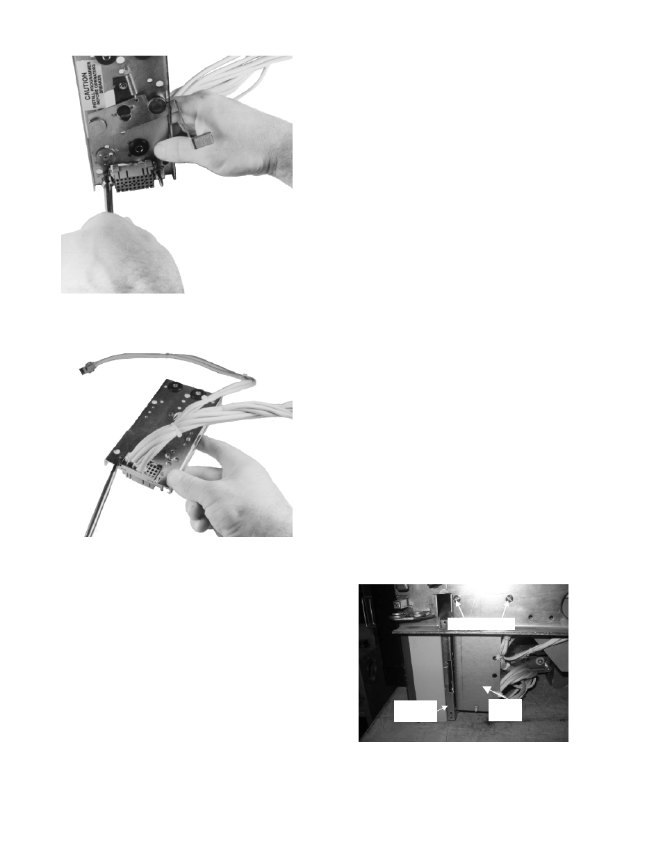
Figure 11. Installing the push nuts onto the guide pins
Figure 12. Locking tabs on mounting plate
Installing the Trip Unit Mounting Plate
1. Take out the programmer mounting plate fully
assembled as shown in figure 13.
2. For LA-Gold breakers, place the two upper
slotted mounting holes in the support bracket
behind the two existing holes in the breaker
frame, as shown in Figure 14. Secure with the
1
/
4
-20 screws, lock washers, and nuts provided.
3. For RL breakers, use tapped hole & slotted hole,
both will accommodate a #10 screw. Secure
plate assembly with provided #10-32 screws,
nuts, lock washers. Figure 14a shows the RL-
2000 setup with screws instead of bolts.
4. Route the four-pin flux shifter connector to the
flux shifter assembly and mate it with the
connector from the flux shifter.
5. Pass the current sensor leads from front to rear
through the hole on the lower left side (viewed
from the rear) of the breaker frame, as shown in
Figures 15 and 16.
6. If the trip unit is to be connected to a communi-
cation network, pass the connector through the
rear-frame hole with the CT leads. Otherwise, tie
it to some convenient point on the breaker frame
with wire ties.
7. If a neutral sensor is to be used in the equip-
ment, pass the corresponding connector through
the rear-frame hole with the CT leads. Other-
wise, tie it to some convenient point on the
breaker frame with wire ties (with the com-
munication connector, if also unused).
8. While breaker is open, adjust the position of
micro switch actuating screw in a manner such
that mincroswitch mounted behind trip unit
mounting plate is not actuated (i.e. switch
activating plunger is released). Lock actuating
screw in this position with lock nut.
Figure 14a: Mounting plate and support
bracket with trip unit (shown on RL-2000)
Support
Bracket
Mounting Screws
Mounting
Plate