GE Industrial Solutions Entelliguard TU, MicroVersaTrip Plus and PM Conversion Kits User Manual
Page 6
6
SECTION 3. BREAKER PREPARATION
The following steps are performed to prepare the
breaker for installation of the new conversion kit.
Unless otherwise indicated, the procedure is the
same for LA-600, LA-800, LA-1600, RL-800, RL-1600,
and RL-2000 breakers.
WARNING:
Before installing the conversion kit, turn
the breaker OFF, disconnect it from all voltage
sources, and discharge the closing springs.
1. Open the breaker and remove it from its enclo-
sure. Carefully place the breaker on a suitable
work surface so that the rear of the breaker is
initially accessible.
2. If the conversion kit is to be installed on a fused
breaker (LAF series), remove the fuse structure
from the upper (line) studs to allow easier access
to the load studs.
3. Loosen the two Allen-head screws securing each
of the primary disconnects to the line (upper) and
load (lower) studs and remove the primary
disconnects, as illustrated in Figures 1 & 1a.
4. Remove the wires from the original current sen-
sors (CTs), if present, and slide off the CTs.
5. Unscrew the knob on the end of the manual
charging handle and pull the handle down part
way. Remove the two bolts holding the escutch-
eon to the breaker frame and lift off the
escutcheon.
6. Carefully position the breaker so that it is resting
on its back on the line and load studs.
7. Remove the two bolts securing the old flux shifter
mounting bracket (if present) to the breaker
frame. One bolt is secured with a nut, the other is
attached to a tapped hole in the frame.
Disconnect the two connectors on the leads to the
trip unit and remove the flux shifter.
8. Remove the three bolts securing the trip unit
mounting bracket (if present) to the breaker
frame. Remove the trip unit and its wiring har-
ness.
Notes:
Prior to installing the new flux shifter on the LA-
Gold breakers remove the old link [14] located as
shown in figure 2. After installing the new flux
shifter, assemble the link back.
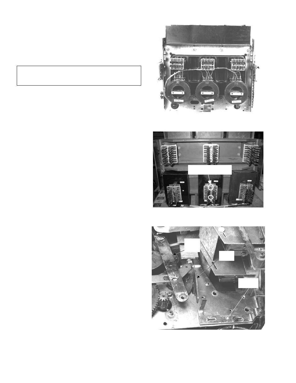
Figure 1. Primary disconnects removed from the lower studs,
showing the original current sensors (LA-1600 shown)
Figure 1a. Primary disconnects removed from the lower studs,
showing the original current sensors (RL-2000 shown)
Figure 2. Original flux shifter and trip unit (Type LTS1 shown)
mounting locations (LA-1600 shown)
Breaker
Reset
Link
Trip
Paddle
Link [14]
Allen-head