GE Industrial Solutions Entelliguard TU, MicroVersaTrip Plus and PM Conversion Kits User Manual
Page 16
16
Note: If communications is not required for this
application, install the two pin wire harness
(supplied with the kit) to provide 24V DC to the
trip unit. Power supply of 24V DC is essential for
advanced functions of the trip unit such as
backlight display, status LED indicator, event log
etc.
SECTION 5. INSTALLING THE TRIP
UNIT
Use the following procedure to install the trip unit.
1. Pull out the locking lever on the trip unit mount-
ing plate until it snaps into the open position, as
shown in Figure 13.
2. Carefully line up the 36-pin connector mounting
pins with the two holes on the sides of the
connector cutout on the rear of the trip unit. The
alignment pin on the rear of the trip unit must fit
through the hole in the locking lever.
3. Push the trip unit against the mounting plate until
it locks into position. The locking lever will
automatically snap back to secure the trip unit.
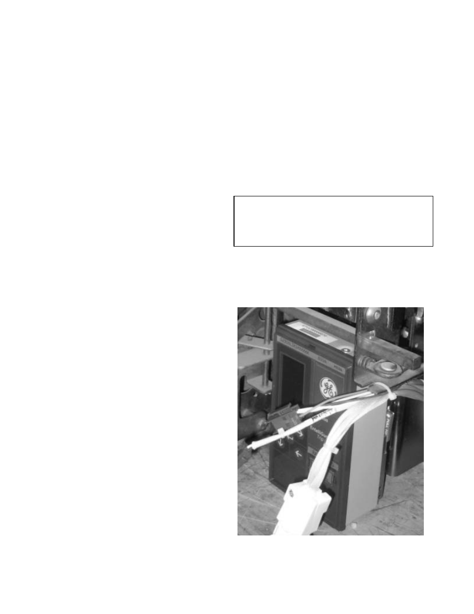
Figure 18 shows an installed trip unit.
CAUTION
: Ensure that the trip unit connector is
seated firmly into the 36-pin connector on the
mounting plate. Improper mating of the connectors
will cause damage to the trip unit, wire harness,
connector, and current sensors.
4. The breaker escutcheon may now be reattached.
To remove the trip unit, slide out the locking lever to
release the alignment pin, then carefully pull the trip
unit straight off the mounting plate.
Figure 18. Trip unit installed on the breaker (RL-1600 shown)