GE Industrial Solutions Entelliguard TU, MicroVersaTrip Plus and PM Conversion Kits User Manual
Page 14
14
Installing the Current Sensors
The current sensors (CTs) must be installed
differently in the two breaker frame sizes.
LA-600, LA-800 and RL-800 Current Sensors
The following procedure is illustrated in Figure 15.
1. Slide two of the CTs over the outer load studs
with their terminals pointing upward. Slide the
other CT over the centerline stud with its
terminals pointing downward.
2. Connect the CT leads from the trip unit to each
CT. The leads are labeled with the letter of the
corresponding pole (A is the right pole from rear
of the breaker, B center, C left), and are also cut to
the appropriate lengths. Attach the white wire to
the terminal marked with a white paint dot on the
A and C (outer) CTs. Attach the black wire to the
terminal marked with a white paint dot on B
(center) CT. This difference is necessary to main-
tain polarity.
3. Reattach the primary disconnect assemblies to all
the studs if the breaker is unfused or to only the
load (lower) studs if the breaker is fused.
4. If the breaker is fused, reinstall the fuse assem-
blies on the upper studs.
LA-1600 Current Sensors
The following procedure is illustrated in Figure 16a.
1. Slide the three current sensors (CTs) over the
lower (load) studs, with the terminals pointing up.
2. Connect the CT leads from the trip unit to each of
the CTs. The leads are labeled with the letter of
the corresponding pole (A is the right pole from
rear of the breaker, B is the center pole, C is the
left pole), and are also cut to the appropriate
lengths. Attach the white wire to the terminal
marked with a white paint dot.
3. Reattach the primary disconnect assemblies to all
the studs if the breaker is unfused or to only the
load (lower) studs if the breaker is fused.
4. If the breaker is fused, reinstall the fuse assem-
blies on the upper studs.
RL-1600 Current Sensors
The following procedure is illustrated in Figure 16b.
1. Slide the three current sensors (CTs) over the
lower (load) studs, with the terminals pointing up.
Identify the left and right pole CTs based on the
location of the tie-wrap as shown in Figure 16b.
Left pole & right pole CTs should be shifted a little
towards center.
2. Connect the CT leads from the trip unit to each of
the CTs. The leads are labeled with the letter of
the corresponding pole (A is the right pole from
rear of the breaker, B is the center, C is the left),
and are also cut to the appropriate lengths. Attach
the white wire to the terminal marked with a
white paint dot.
3. Reattach the primary disconnect assemblies to all
the studs if the breaker is unfused or to only the
load (lower) studs if the breaker is fused.
4. If the breaker is fused, reinstall the fuse assem-
blies on the upper studs.
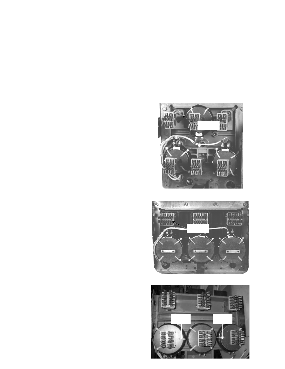
Figure 15. Installing the CTs on an LA-600 or LA-800 breaker
Figure 16a. Installing the CTs on an LA-1600 breaker.
CT Wire Exit
Hole
CT Wire Exit
Hole
Identify
Left Pole
Identify
Right Pole