GE Industrial Solutions Entelliguard TU, MicroVersaTrip Plus and PM Conversion Kits User Manual
Page 15
15
Figure 16b. Installing the CTs on an RL-1600 breaker
RL-2000 Current Sensors
The following procedure is illustrated in Figure 16c.
1. Slide the three current sensors (CTs) over the
lower (load) studs, with the terminals pointing
up.
2. Connect the CT leads from the trip unit to
each of the CTs. The leads are labeled with
the letter of the corresponding pole (A is the
right pole from rear of the breaker, B is the
center, C is the left), and are also cut to the
appropriate lengths. Attach the white wire to
the terminal marked with a white paint dot.
3. Reattach the primary disconnect assemblies
to all the studs if the breaker is unfused or to
only the load (lower) studs if the breaker is
fused.
4. If the breaker is fused, reinstall the fuse
assemblies on the upper studs.
Installing the Communications Harness
The communications harness is used if the trip unit is
to communicate with a power management control
system. The communications connector, included in
the trip unit wiring harness, is mounted with the
supplied angle bracket. This bracket has two small
holes on one arm for attaching with screws to a
convenient spot on the breaker frame and a large
rectangular hole in the other arm for mounting the
connector.
The communications connector should be installed
on the breaker on the same side as the breaker
compartment’s door hinge, to protect it from damage
when the compartment door is opened or closed.
Attach the supplied caution labels, shown in Figure
17, to both the breaker and the compartment door as
a warning to disconnect the communications harness
before removing the breaker from the compartment.
Figure 17. Caution label to be applied to the breaker
and compartment door
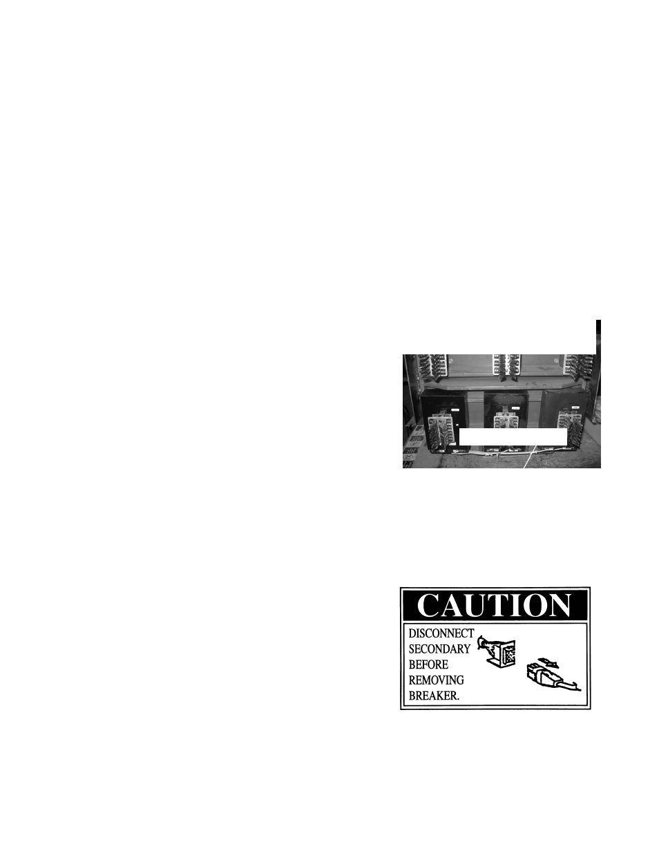
Figure 16c: Installing the CTs on an RL-
2000 breaker
Wiring harness below CT’s