3 front doors, Drawout operation, Operation – GE Industrial Solutions Entellisys Installation User Manual
Page 60: Removal and installation, Door removal, Door installation
54
Entellisys Low Voltage Switchgear
Chapter 7. Operating the Switchgear
Drawout Operation
All breakers are supported on the drawout rails mounted on
the sidewalls of the breaker compartments. On EntelliGuard
breakers, two wheels on each side of the breaker rest on each
drawout rail.
Motion is provided by a mechanism mounted on the breaker.
This mechanism drives racking cams that engage pins
anchored to each side of the compartment.
The cams are driven by a removable racking handle that
engages the mechanism. On small frame breakers, the
handle is inserted through an opening in the breaker
escutcheon; on large frame breakers, the handle is inserted in
an opening in the upper right side of the door.
Turning the handle in a clockwise direction drives the
breaker into the compartment. As the breaker disconnect
fingers engage the stationary studs, a high force will be felt.
Turn the racking handle as far as it will go to be sure the
disconnect fingers are completely engaged.
The position indicator in the breaker escutcheon gives the
position of the breaker as it moves through the door cutout.
7-3 Front Doors
Operation
The front access doors on all standard Entellisys Switchgear
are hinged and equipped with a ¼-turn latch, Fig. 7-3. To
open the door, rotate the knob clockwise ¼ turn.
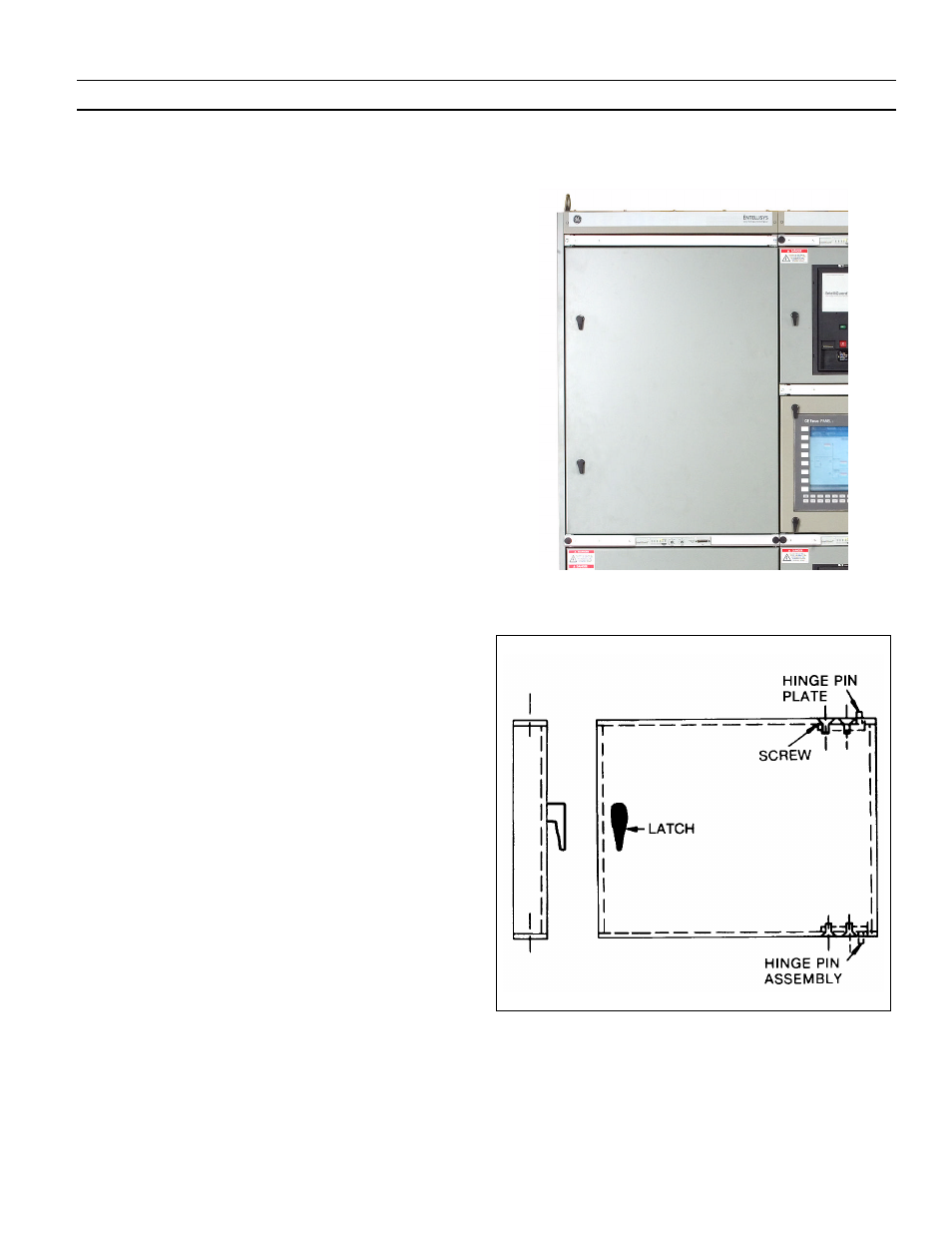
Removal and Installation
Refer to Fig. 7-3 and remove/install switchgear front doors.
Door Removal
To remove the Entellisys Switchgear door, proceed as follows:
1.
Open door.
2.
Loosen the two screws holding the top hinge pin plate
and allow the pin to drop out of the hinge block. See Fig.
7-3.
3.
Move the top of the door away from the switchgear,
avoiding the door stop and lift the door out of the lower
hinge pin socket. Retain the washer from the bottom
hinge pin.
Door Installation
To install the Entellisys Switchgear door, proceed as follows:
1.
Insert washer, then place lower hinge pin into hinge pin
socket on switchgear. See Fig. 7-3.
2.
Swing door open, position behind door stop and align
hinge pin socket.
3.
Insert the hinge pin into the upper hinge block and
tighten the two screws.
4.
Close the door.
Fig. 7-2. Entellisys switchgear front access doors are hinged with a
rotary-type latch
Fig. 7-3. Drawing showing front access details