10 bus area, Busing system – GE Industrial Solutions Entellisys Installation User Manual
Page 25
19
Entellisys Low Voltage Switchgear
Chapter 3. Description
3-10 Bus Area
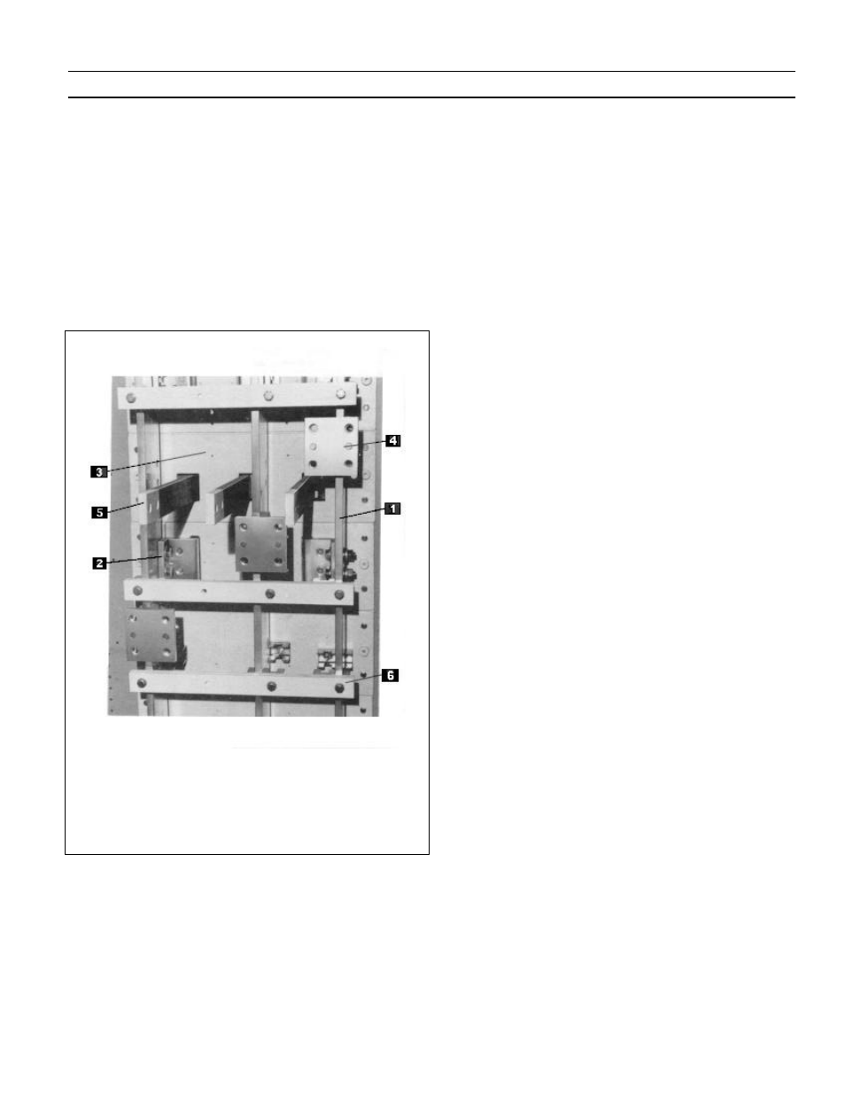
The bus area,
Fig.
3-14, contains the main horizontal bus and
vertical riser bus bars (1) for the particular section. The
vertical bus bars are supported at the breaker run-ins (2)
that are bolted to the molded bases (3) that form the rear
wall of the breaker compartment. The horizontal bus bars
are supported by the power connectors (4), which are bolted
to the vertical bus bars. All bolted supports and connections
are accessible from the rear for maintenance. The bus area is
fully isolated from the breaker, instrument and auxiliary
compartments by the molded bases or glass polyester sheet.
1 Vertical riser bus
2. Run-ins to breaker compartment
3. Molded base
4. Power Connector
5. Run-backs from breaker compartment
6. Short-circuit brace
Fig. 3-14. Bus construction
Busing System
Bus bars are fully tin-plated copper with bolted joints. The
standard construction is open bus. A barrier system (Bus
compartmentalization) that isolates the main and vertical
bus bars from the cable area is available as an option. All
run-backs (load-side power conductors) from the breaker
compartment to the cable termination area are covered with
non-PVC insulated tubing.
The typical arrangement is shown in
Fig.
3-15.
The standard bracing is 65,000 amperes, RMS symmetrical.
Bracing for 100,000, 150,000 and 200,000 amperes, RMS
symmetrical is available as an option.
In general, when the switchgear equipment has no more than
four sections or does not exceed 10 feet in length, it will be
shipped as one complete lineup. In such cases, the only field
assembly would be to a close-coupled transformer if, the
switchgear were part of a Load Center Unit Substation. If,
because of shipping and/or handling considerations, the
equipment cannot be handled in one piece, it can be split into
two or more shipping sections at the factory. The individual
shipping splits require both mechanical and electrical
connections between sections to be made in the field. At
these shipping splits, provisions are made for bolting all
buses and making the necessary electrical and mechanical
connections. These are described in Chapter 4 of this
publication.
On main and tie breakers, the bus area,
Fig.
3-15, is divided
into an upper (1) and lower (2) section by a glass reinforced
polyester isolation barrier (3). For typical unit substation
main circuit breakers, the upper section contains the
incoming line bus (4). The lower section of the bus area
contains the load side main bus (5) (protected by the main
breaker) that feeds all sections of the switchgear equipment.
Similarly, barriers at tie breakers isolate the two main bus
sections from each other.