GE Industrial Solutions Entellisys Installation User Manual
Page 35
29
Entellisys Low Voltage Switchgear
Chapter 4. Equipment Installation
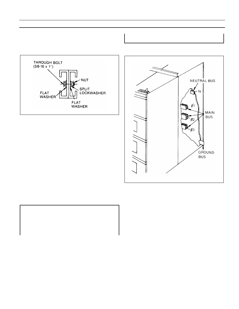
Fig. 4-7 illustrates the installation of the through-bolts. The
through-bolts are in the front and rear compartments. The
nut and bolt assembly should be tightened with a torque of
25-30 ft-lbs.
Fig. 4-7. Through-bolt installation
All of the hardware required for assembling the equipment
across the shipping splits is furnished with the equipment. If
a transformer is included in the line-up of equipment, the
transformer flange should be aligned with the opening in the
side of the transition compartment and fastened together
using the 3/8-16 bolts, nuts and washers supplied with
switchgear. The fastener assembly should be tightened with
a torque of 25-30 ft-lbs.
4.
COMPLETE THE ELECTRICAL
INTERCONNECTIONS - After completing the
mechanical connections between the several sections of
equipment, the electrical interconnections should be
completed. This includes the installation of splice
plates for the main bus bars, the neutral bus, and the
ground bus in addition to the Entellisys control and
communication circuitry.
WARNING: All switchgear equipment must be
adequately grounded for safety. Failure to ground
equipment properly may result in serious injury.
ADVERTISSEMENT: Tout l’équipement du dispositif de
commutation doit être mis à la terre adéquatement de
manière sécutaire. Des blessures sérieuses peuvent
survenir si l’on omet de mettre l’équipement à la terre
correctement.
Fig. 4-8 illustrates the general location of the buses that
must be spliced across the shipping splits.
Fig. 4-8. Typical location of buses at shipping split