Prior to installation, Installation procedures – GE Industrial Solutions Entellisys Installation User Manual
Page 48
42
Entellisys Low Voltage Switchgear
Chapter 5. Installing and Removing Circuit Breakers
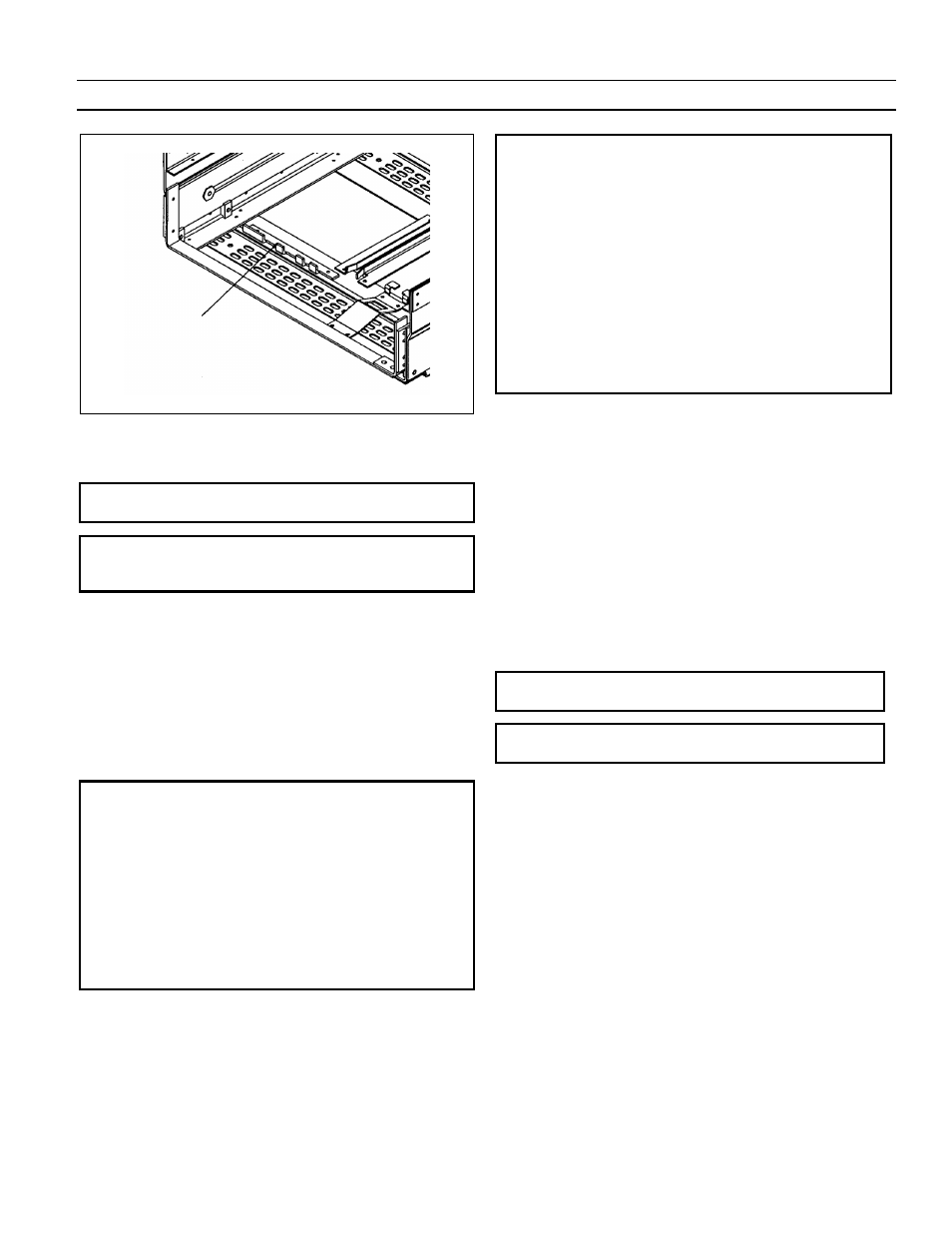
Fig. 5-3. Isometric view of rejection angle used in EG-32/40/50
compartments
NOTE: If a breaker is rejected by the rejection pins, check
the breaker type and rating against the job drawing.
NOTE: Si un disjoncteur est rejeté par les pins
coulissants, vérifier de quel type est le disjoncteur ainsi
que le calibrage en rapport avec le plan de la tâche.
The complete rejection pin pattern code is included in
Appendix B.
5-2 Installing EG-08/16/20 Circuit
Breakers
Prior to Installation
Prior to lifting a breaker to its intended compartment
location, observe the following precautions:
Precautions:
1.
Check the compartment to ensure that it is free of
foreign objects.
2.
Verify that the breaker is the correct type for that
compartment.
3.
Ensure that the breaker is OPEN.
4.
Apply a thin fresh coat of GE lubricating grease
D6A15A2 to the breakers primary disconnects.
5.
Ensure that the racking forks on the breaker are
correctly positioned for initial engagement with the
pins in the compartment. To do this, insert the
racking handle and rotate it fully counterclockwise.
Précautions:
• Vérifier le compartiment afin de s’assurer qui’il est
libre d’objets étrangers.
• Vérifier que le disjoncteur est du genre correct pour ce
compartiment.
• Assurez-vous que le disjoncteur est en position OPEN.
• Appliquer une mince couche fraîche de graisse
lubrifiante GE D6A15A2 aux débranchements
primaires du disjoncteur.
• Assurez-vous que les cames de montage du disjoncteur
soient positionnées correctement en vue de
l’engagment initial avec les goujons du compartiment.
Pour ce faire, insérer la poignée de montage et lui faire
effectuer une rotation complète dans le sens des
aiguilles d’une montre.
Installation Procedures
To install the EntelliGuard circuit breaker, proceed as
follows:
1.
Carefully place the breaker in front of the section in
which it is to be installed. See Fig. 5-4.
2.
Open the breaker compartment door by rotating the
door latch assembly ¼ turn clockwise.
3.
Using the switchgear hoist or a suitable lifting
mechanism and the appropriate spreader, raise the
breaker above the elevation of the rails. See Fig. 5-5.
The lifting spreader for 800A, 1600A & 2000A AKR
breakers cannot be used with 800A, 1600A & 2000A
EntelliGuard breakers.
WARNING: Do not stand under the circuit breaker
during the hoisting operation.
ADVERTISSEMENT: Il est interdit de se tenir sous le
disjoncteur durant l’opération de levage.
REJECTION
ANGLE