GE Industrial Solutions Entellisys Installation User Manual
Page 51
45
Entellisys Low Voltage Switchgear
Chapter 5. Installing and Removing Circuit Breakers
5-3 Installing EG-32/40/50 Circuit
Breakers
WARNING: Do not stand under the circuit breaker
during the hoisting operation.
ADVERTISSEMENT: Il est interdit de se tenir sous le
disjoncteur durant l’opération de levage.
CAUTION: When using the switchgear hoist, do not un-
wind the cable completely from the drum. To lift the
breaker, turn the hoist operating crank clockwise. To lower
the breaker, turn the hoist operating crank counter-
clockwise.
ATTENTION: Il ne faut pas dérouler complètement le
câble du cylindre lorsque l’on utilisse le treuil du dispositif
de commutation. Tourner la manivelle opérant le treuil
dans le sens des aiguilles d’une montre pour soulever le
disjoncteur. Tourner la manivelle opérant le treuil dans le
sens contraire des aiguilles d’une montre pour abaisser le
disjoncteur.
Installation Procedure
To position the EGS-32/40/50 circuit breaker on the drawout
rails, proceed as follows:
1.
Carefully place the breaker in front of the section in
which it is to be installed, See fig. 5-4.
2.
Open the breaker compartment door by rotating the
door latch assembly ¼ turn clockwise.
3.
Using the switchgear hoist or a suitable lifting
mechanism and the appropriate spreader for EG-
32/40/50, raise the breaker above the elevation of the
rails. See Fig. 5-5.
4.
Pull the drawout rails all the way out to its WITH-
DRAWN limit. The rail pin will be positioned at the
back of the rail slot.
5.
Slowly lower and guide the breaker to allow the 4
breaker wheels to align with the rails. See Fig. 5-7.
Remove the lifting device. The breaker is now
positioned on the drawout rails.
6.
Roll the breaker into the compartment until the racking
cams touch the racking pin and the spring discharge
stop engages. This is the DISCONNECT position. At
this point, the racking cams are positioned to engage
the fixed racking pins in the compartment, ready to
begin the racking motion. If the incorrect breaker has
been installed, the interference pins on the breaker will
interfere with the rejection teeth in the compartment
prior to reaching the disconnect position (Fig. 5-10).
7.
Slide rails back into compartment. Close the
compartment door and rotate latch ¼ turn counter-
clockwise.
8.
With the EG-32/40/50 breakers rotate the racking
access cover in the door and engage the racking handle
9.
Rotate the handle clockwise as far as it will go. As you
rotate the handle clockwise, the breaker will travel from
the disconnect, through the test position (you will notice
an audible click as the secondary disconnects engage),
and then into the connect position. The breaker
position can be seen on the indicator, located on the
breaker escutcheon.
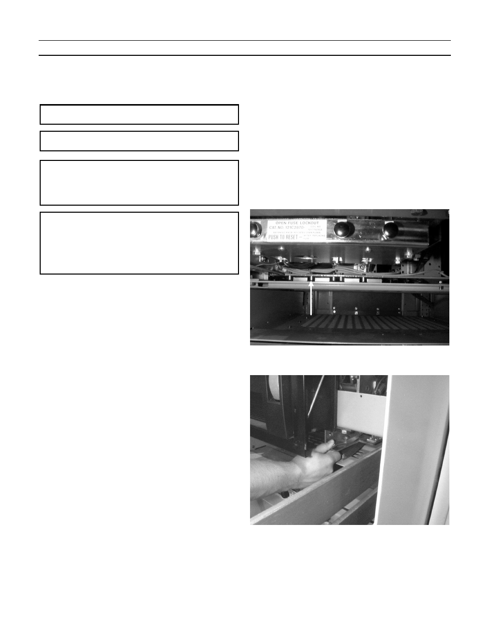
Fig. 5-10. Rating rejection bracket on EG-32/40/50
Fig. 5-11. Spring discharge interlock used on manually and electrically
operated breakers