GE Industrial Solutions Entellisys Installation User Manual
Page 20
14
Entellisys Low Voltage Switchgear
Chapter 3. Description
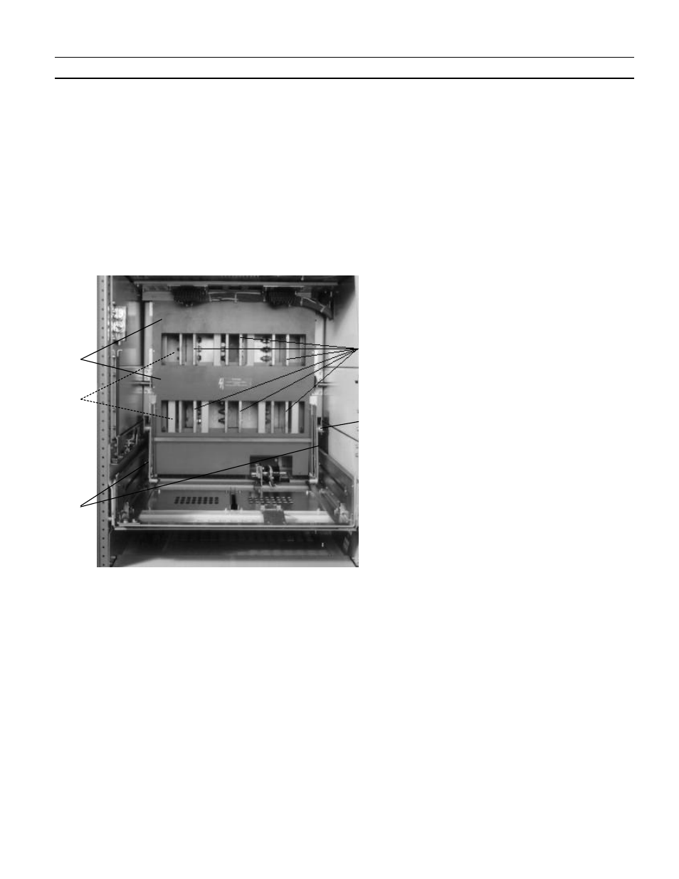
The shutters are partially retracted when the breaker is in
the Disconnect Position. As the circuit breaker is racked from
the Disconnect Position to the Test Position, the rear of the
circuit breaker frame depresses the shutter operating lever
(3) to cause the shutters to fully retract. The operating lever
springs (4) cause the operating lever (3) to remain in contact
with the circuit breaker frame during operation. As the
breaker is racked from the Test Position to the Connected
Position, the shutters remain fully retracted.
Fig. 3-7 also shows the shutter assembly with the shutters
manually retracted to show the location of the primary
disconnect stabs (5) behind the shutter assembly.
Circuit breakers mounted in 22-inch wide compartments
(EG-08, EG-16, EG-20) are supported on drawout rails (7),
Fig.
3-5. Larger EG-32 and EG-40 circuit breakers and fuse
rollout carriages are installed in 30-inch wide compartments
and are supported on drawout rails (5),
Fig.
3-6. The EG-50
circuit breaker is installed in a 38-inch wide compartment
and is supported on drawout rails (similar to Item 5, Fig. 3-
6).
Fig. 3-7. Entellisys primary disconnect shutter assembly (30-inch wide compartment).
Shutters manually retracted
1. Stationary barrier
2. Shutters (not visible in
retracted position)
3. Operating lever
4. Operating lever springs
5. Primary disconnect stabs
5
3
1
2
4