Galaxy gateway, Operational note, Preparation – GE Industrial Solutions Galaxy Vector Rack Mounted Controller J85501M-1 User Manual
Page 75: A - 5, Figure a-4: installing the gateway, Hd r1 h d r2, Red/ rojo blk /ne gro
Galaxy Rack-Mounted Vector Controller J85501M-1
Issue 2 January 2008
Communications Appendix A - 5
Galaxy Gateway
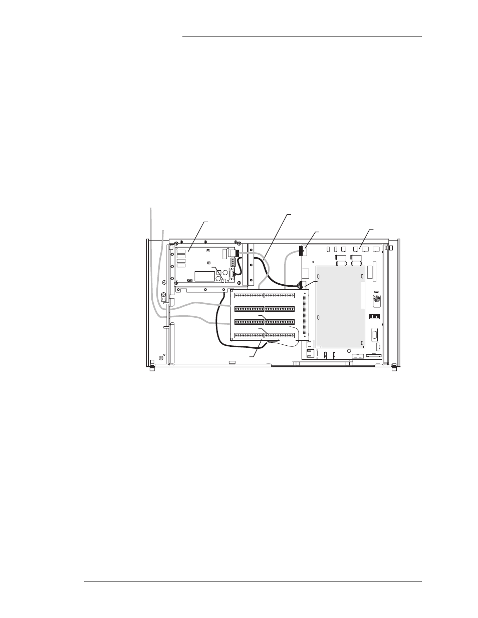
Figure A-2 shows the Galaxy Gateway installation and cabling
procedures required in a J85501M-1 Vector controller, including
computer and Galaxy Gateway configuration. Note that only one
mounting position is available for a remote option; either a
Gateway (EBW) or modem (BSM) board.
Operational Note
If J5 is connected to an option board (EBV1, BSM3 or BSM4),
then a terminal is connected to DB9 connector J4, the J4 RS-232
connection takes precedence. This will stop the RS-232
communication through J5 until the connection to J4 is removed.
Figure A-4: Installing the Gateway
EBW1 Gateway Board
BUJ Board
Alarm Termination Board
HDR3
H
D
R1
H
D
R2
J4
S1
FH1
P2
J6
J9
P5
J5
-
+
-
+
J1
3
J1
4
1
J21
1
J15
1
1
1
J19
1
J18
J20
J1
7
J1
6
BU
Z1
J7
J8
J3
J1
2
2
8
1
1
8
A1
B1
C1
A32
C32
1
1
1
1
1
1
2
3
4
5
6
7
8
1
0
TERM
RES
RS
48
5
POW
E
R
OPT RS232
11
/3
A
AB
S
FU
SE
AMJ
FAJ
LVD1
LVD2
THERM 2
THERM 1
FORCE ON
AUTO
FORCE ON
24V
48V
48V
24V
24V
48V
24V
48V
ON
OFF
LO
CA
L RS
23
2
KEY PAD
DISPLAY
R10
TJ
2
TJ1
RED/
ROJO
BLK
/NE
GRO
PLANT V
SHUNT
848575841 Controller
Interface Cable
848722096
BUJ Power Cable
CAT5 LAN
Cable
848575841
EBW Power
Cable*
J5
P1
P5
TB2*
Red
TB4*
Red: ABS - TB4 Pin 1,3,5,9 or 11
Black: DG - TB2 Pin 11 or 12
*Power Cable Connections
Black
Preparation
The following Network Configuration Parameters must be
obtained from your Network Administrator before starting:
•
IP address
•
Subnet mask
•
Host name
•
Gateway IP address
Note: Host and Gateway are optional.