Buj terminal connection board, Connection board, S1.2: software mode – GE Industrial Solutions Galaxy Vector Rack Mounted Controller J85501M-1 User Manual
Page 21
Galaxy Rack-Mounted Vector Controller J85501M-1
Issue 2 January 2008
Product Description 2 - 7
BUJ Terminal
Connection
Board
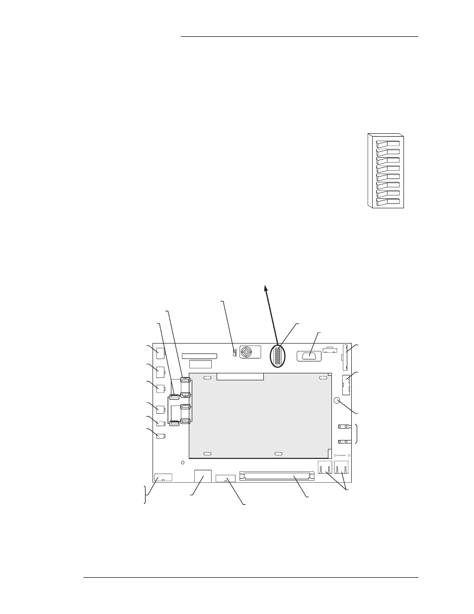
Figure 2-6 shows the BUJ Terminal Connection Board. The
following pages describe the required connections. Note: To
make connections to the 1U_ALM Board terminal blocks, pull
the front of the insulating cover off of the mounting posts.
Figure 2-6: J85501M-1 Vector Controller / BUJ Terminal Connection Board
HDR3
HDR1
HDR2
J4
S1
FH1
P2
J6
J9
P5
J5
-
+
-
+
J13
J14
1
J21
1
J1
5
1
1
1
J1
9
1
J18
J2
0
J17
J16
BUZ1
J7
J8
J3
J1
2
2
8
1
1
8
A1
B1
C1
A32
C32
1
1
1
1
1
1
2
3
4
5
6
7
8
1
0
TERM RES
RS485
POWER
OPT
RS
232
1 1/3A
ABS FUSE
AMJ
FAJ
LV
D
1
LV
D
2
THE
RM 2
THE
RM 1
FOR
CE ON
AUTO
FOR
CE ON
24V
48V
48V
24V
24V
48V
24V
48V
ON
OFF
LOCAL RS232
KE
Y PAD
DISP
LAY
R10
BUJ Board
GCM Board
Keypad
Display
Display Contrast Control
Potentiometer
J7,J8: RS-485 to Rectifiers
J5: BSM3/BSM4 Modem
or EBW1 Ethernet Board
P2: Alarm Board
J15,J20: LVD Force-On Jumpers
J11,J12,J18,J19:
24V / 48V Selection Jumpers
J21: Manual Buzzer
Disable Jumper
J4: Local RS-232 DB9 Port
S1: DIP Switch
ABS Fuse
P5: Power
Shunt
Vsense
J16: AMJ Input
J17: FAJ Input
J13: LVD1
J14: LVD2
J1: Thermal Probe 1
or 210E
J3: Thermal Probe 2
or 210E
System Voltage and
Shunt Test Points
S1.2: Software Mode
1,2
S1.3: Option Card Availability
S1.1: Front Panel Configuration
0
1
0
1
0
1
- Enabled (shown)
- Disabled
- Standard (shown)
- Custom Default Configuration Parameters
3
- Modem
- Galaxy Gateway Card (Internet)
S1.4: Rectifier Class
0
1
- Standard GPS Rectifiers
- NP/AC3000 Rectifiers
S1.5: Alarm Contact Select
1
S1 DIP Switch Settings
S1.7: Plant Battery Test
0
1
0
1
0
1
- Standard HV, High Voltage
- VLV, Very Low Voltage
- Disabled (shown)
- Active
- Normal (shown)
- Reset Display
S1.6: - Set to 0
S1.8: - Display Reset
4
1. Setting both SW1.2 and SW1.5 to "1" will result in activating the HV alarm cont act.
2. SW1.2 setting will only be read by the software when the GCM is powered up.
3. HV alarm contacts used for 2ACF alarm instead of HV alarm.
4. Cycling from "0" to "1" and back to "0" will reset the display.
S1
8
7
6
5
4
3
2
1
0
1
TJ2
TJ1
RED/ROJO
BLK/NEGRO
PLAN
T
V
SH
U
N
T