Control signal inputs, Thermal probe connections, Rectifier connections – GE Industrial Solutions Galaxy Vector Rack Mounted Controller J85501M-1 User Manual
Page 25: Communication port, Table 2-h: buj1 control signal inputs, Table 2-i: rth alm, rth almr terminals
Galaxy Rack-Mounted Vector Controller J85501M-1
Issue 2 January 2008
Product Description 2 - 11
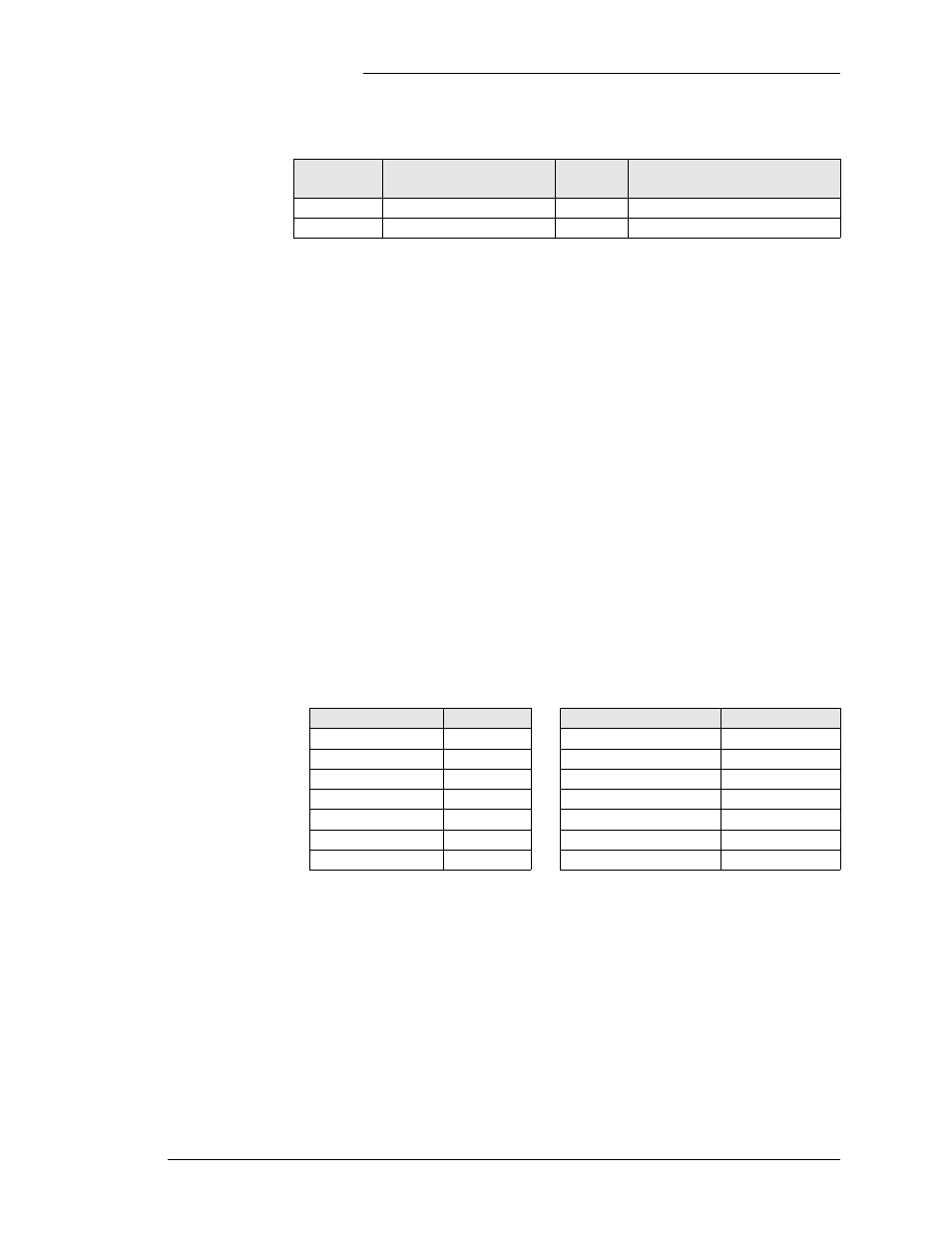
Control Signal Inputs
Table 2-H: BUJ1 Control Signal Inputs
Signal
Description
Alarm
Board
Alarm Asserted
PBT
Plant Battery Test
TB4.8
Closure to PBT_RTN (TB4.7)
RO
Reserve Operation
TB4.4
Closure to Batt
See Section 3 for details on the Plant Battery Test and Reserve
Operation features.
Thermal Probe
Connections
Four thermistor or 210E module inputs are provided on the
alarm termination board, and two thermal probe inputs are
provided at J1 and J3 on the BUJ1. These connectors will accept
standard Lineage Power thermal cables or 210E cables. J1 and
J3 provide cable access to RTH1 and RTH2 thermal probes,
respectively. If connections are made at J1 and J3 then they
should not be made at the terminal blocks and vice versa. Access
to all four thermistors is available at the terminal block. Each
thermistor is connected to the RTH#+ and RTN#, where # = 1
through 4. A strap is required across RTH#+ and EN#+ for each
thermistor input used. The strap is not required when using 210E
modules.
RTH ALM, RTH ALMR: Thermistor alarm input and return
from 210E module. See Section 4 for 210E module connections.
Table 2-I: RTH ALM, RTH ALMR Terminals
Signal
Terminal
Signal
Terminal
RTH1_EN
TB6.7
RTH3_RTN
TB5.11
RTH1_RTN
TB6.8
RTH3+
TB5.12
RTH1+
TB6.9
RTH4_EN
TB5.6
RTH2_EN
TB6.3
RTH4_RTN
TB5.7
TRH2.RTN
TB6.4
RTH4+
TB5.8
RTH2+
TB6.5
RTH_ALM
TB6.11
RTH3_EN
TB5.10
RTH_ALMR
TB6.12
Rectifier Connections
J7, J8: RJ45 connectors for the serial RS-485 rectifier and
equipment interface. These are parallel connectors and can be
used interchangeably.
Communication Port
J5: RS-232 serial communication port used with the optional
BSM3 modem boards or EBW1 Gateway board (see Appendix
A).